SLUUC73A March 2020 – December 2023 BQ25616
2.2 Equipment Setup
Use the following instructions to set up the equipment:
- Review EVM connections in Table 1-2.
- Set PS1 for 5-V DC, 3-A current limit and then turn off the supply.
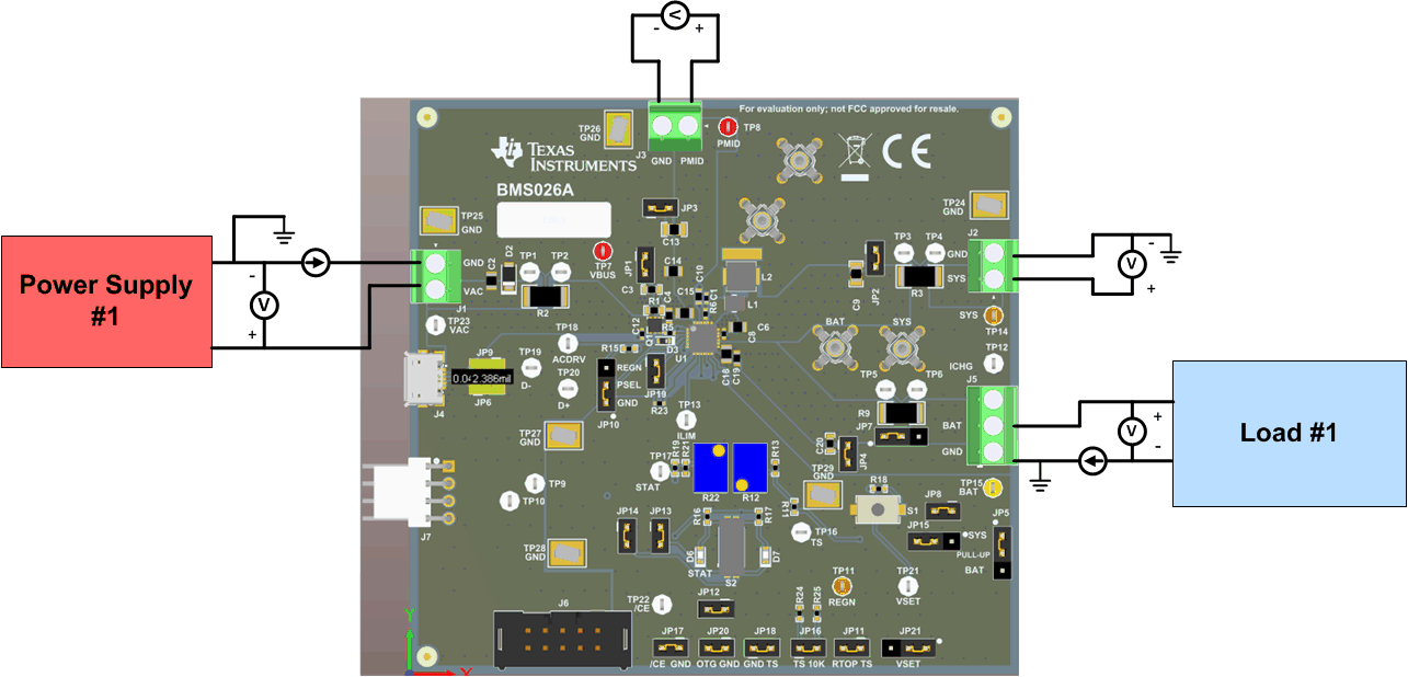
- Connect the output of PS1 in series with a current meter to J1 (VAC and GND).
- Connect a voltage meter across TP7 (VBUS) and TP25 (PGND), or across J1.
- Turn on Load #1, set to constant voltage mode, and output to 3.7-V. Disable Load. Connect Load in series with a current meter (multimeter), ground side, to J5 (BATTERY and GND) as shown in Figure 2-1.
- Connect one voltage meter across TP15 (BAT) and TP24 (PGND), or across J4-2 and J4-1 as shown in Figure 2-1.
- Connect one voltage meter across TP14 (SYS) and TP24 (PGND), or across J2-1 and J2-2 as shown in Figure 2-1.
- Install shunts as shown in Table 1-3.
 Figure 2-1 Original Test Setup for BMS026 EVM