SLUUCF7 April 2021 BQ25960
2.4.3 Switched Cap Mode Charge Verification
Use the following steps to verify battery charging in switched cap mode.
- Make sure the steps in Section 2.4.1 and Section 2.4.2 have been followed.
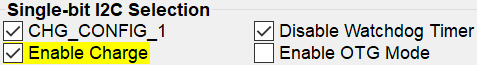
- Check the "CHG_CONFIG_1" box, and then click "Enable Charge".
After enabling charge, the output current flowing into Load #1 should be about
2x the input current flowing out of PS1.
- Change the charge current:
By increasing the input voltage, the output current should increase together with the input current. The output current should always be about 2x the input current. - To stop charging, deselect the "Enable Charge" box. The input current and the output current should both fall to zero.