SNLA246C October 2015 – April 2024 DP83867CR , DP83867CS , DP83867E , DP83867IR , DP83867IS
- 1
- Trademarks
- 1Introduction
- 2Troubleshooting the Application
-
3Application Specific
Debugs
- 3.1 Improving Link-up Margins for Short Cables
- 3.2 Improving Link Margins across Different Channels
- 3.3 Link up in 100Mbps Full Duplex Force Mode
- 3.4 Unstable Link Up Debug in 1Gbps communication
- 3.5 DP83867PHY and DP83867PHY Cannot Link Up in 1Gbps
- 3.6 Compliance Debug
- 3.7 EMC Debug
- 3.8 Tools and References
- 4Conclusion
- 5References
- 6Revision History
2.6 Built-in Self Test With Various Loopback Modes
Loopback feature for debug:
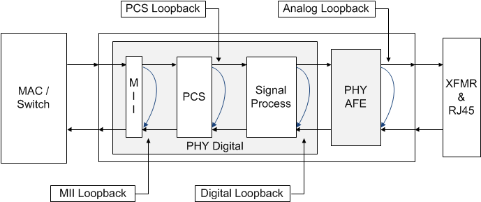
Loopback mode could determine the communication issue occur on MAC < -- > PHY or PHY < -- > PHY. MII loopack, PCS loopback, Digital Loopback, and Analog Loopback could isolate the PHY < -- > PHY communication. Reverse Loopback could isolate the MAC < -- > PHY communication. The following diagrams illustrate the various loopback mode that DP83867 have:
 Figure 2-9 Block
Diagram, Loopback Modes
 Figure 2-10 Block
Diagram, Reverse Loopback Mode
Figure 2-10 Block
Diagram, Reverse Loopback ModeAnalog loopback is typically used to verify the PHY's full internal data path, while reverse loopback is used with a link partner to verify the data path along the MDI.
Transmitting and Receiving Packets with the MAC:
If generating and checking packets with the MAC is possible, and the PHY has a working link partner with reverse loopback capability, verify the full data path as follows:
- Power and connect the PHY to the MAC and a working link partner.
- Enable reverse loopback on the link partner (for DP83867 link partner, write 0x16 to 0020).
- Transmit test packets from the MAC to the PHY.
- Verify the MAC receives the same test packets.
If the MAC receives the same test packets transmitted without issue, the full data path through MAC → PHY → MDI is valid. If this test does not pass, perform analog loopback to isolate the issue along the data path:
- Power and connect the PHY to the MAC.
- Enable analog loopback on the PHY (write 0x16 to 0008).
- Transmit test packets from the MAC to the PHY.
- Verify the MAC receives the same test packets.
If the MAC receives the same test packets, the data path through MAC → PHY is valid, and the issue has been isolated to the MDI data path. If this test does not pass, the issue could be on the MAC interface or the internal data path. To verify the MAC interface, refer to Debugging MAC Interface. To verify the internal data path, perform PRBS with analog loopback using the following script.
Transmitting and Receiving Packets with BIST:
This device incorporates an internal PRBS Built-in Self Test (BIST) circuit to accommodate in-circuit testing or diagnostics. The BIST circuit can be used to test the integrity of the transmit and receive data paths. BIST can be performed using various loopback modes to isolate any issues to specific parts of the data path. The BIST generates packetized data with variable content and IPG.

If generating and checking packets with the MAC is not possible, use PRBS packet generation and checking functionalities to verify the data path. Perform reverse loopback with PRBS and a working link partner as follows:
- Power and connect the PHY to a link partner.
- Enable PRBS packet generation on the PHY (write 0x16 to 5000).
- Enable reverse loopback on the link partner (for DP83867 link partner, write 0x16 to 0020).
- Wait at least one second, then check PRBS lock status on the PHY (read register 0x17[11:10]).
If register 0x17[11] is high, the data path through PHY → MDI is valid. If this test does not pass, the issue could be on the PHY's internal data path or the MDI. To verify the internal data path, perform PRBS with analog loopback using the following script. If the internal data path is valid, then the issue is isolated to the MDI (assuming the link partner is working).
The following is an example sequence of register reads and writes to perform BIST with analog loopback in 10Mbps:
// This is how you make a comment. All scripts must start with 'begin'
begin
// hard reset
001F 8000
// disable auto-neg, force 10Mbps (1)
0000 0100
// enable analog loopback (2)
0016 0008
// force mdi mode for 10/100 Mbps (not relevant for 1000Mbps)
0010 5008
// loopback configuration register required
00FE E720
// enable packet gen, keep analog loopback (3)
0016 5008

// (1)
// for 100Mbps, write 0000 to 2100
// for 1000Mbps, write 0000 to 0140
// (2)
// for digital loopback, write 0016 to 0004
// for PCS loopback, write 0016 to 0003
// (3)
// for packet generation with digital loopback, write 0016 to 5004
// for packet generation with PCS loopback, write 0016 to 5003
end
Reference the annotated (1-3) register writes if testing in different loopback modes or speeds. Wait at least one second before the following reads/writes to allow for PRBS to transmit packets.
begin
// lock byte count
0072 0201
// check lock status, # of packets received, and # of errors
0017
0071
0072
// enable continuous mode packet counting
0016 D004
// update packet counter with current value (4)
0072 0201
// read packet counter (5)
0071
// soft reset
001F 4000
// Repeat (4) and (5) as desired to verify packet count changing for each counter update
end
Register 0x17[11] indicates whether PRBS was able to successfully receive the same transmitted data through the given data path.