SNLA416A September 2022 – February 2024 DS90UB960-Q1 , HD3SS3212-Q1
4 Implementation of Switching Protocol
Prior to switching, disable the deserializer output to prevent the system from entering an error handling or fail-safe mode. Switching between cameras while data is actively being transmitted is not recommended. Implement the following protocol when multiplexing between channels.
Analog LaunchPad Program
# Digital reset at initialization
        board.WriteI2C(desAddr,0x01,0x01)

# Enable CSI-2 output and forwarding (steps below)
        board.WriteI2C(desAddr,0x32,0x01) # Select CSI-2 port 0
        board.WriteI2C(desAddr,0x33,0x03) # Enable CSI-2 output with continuous clock mode
        board.WriteI2C(desAddr,0x20,0x00) # Forward all CSI-2 to port 0

# Before switching the MUX, disable the associated port and forwarding
        board.WriteI2C(desAddr,0x20,0xF0) # Disable forwarding
        board.WriteI2C(desAddr,0x0C,0x00) # Disable the RX port receiver

# After switching the MUX, restart the forwarding and the port receiver.
        board.WriteI2C(desAddr,0x0C,0x0F) # Enable the RX port receiver
        time.sleep(0.1) # Allow time for the port to re-lock
        board.WriteI2C(desAddr,0x20,0x00) # Enable forwarding

# The switching protocol above disables forwarding for all channels. Depending on the application, deactivating only the multiplexed channel is sufficient.

For Example:
        # Disable forwarding of RX Port 2
        board.WriteI2C(desAddr, 0x20, 0x40)

        # Disable Port 2 Receiver
        board.WriteI2C(desAddr, 0x0C, 0x0B)
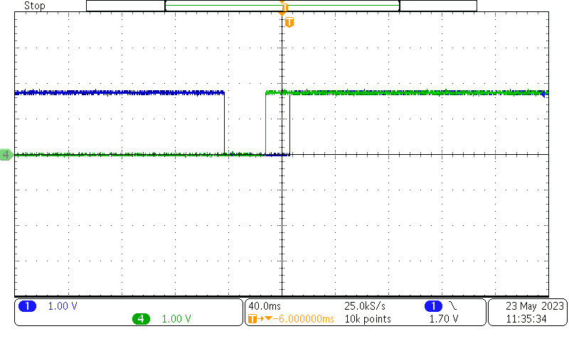
Figure 4-1 demonstrates the switching time from when the MUX is switched and the link is re-established. The initialization time of the Imager via I2C also needs to be accounted for in addition to the time it takes to re-establish the link, and once initialization of the camera is complete, the output is seen at the processor.
