SNLA416A September 2022 – February 2024 DS90UB960-Q1 , HD3SS3212-Q1
3 Multiplexing Execution and Setup
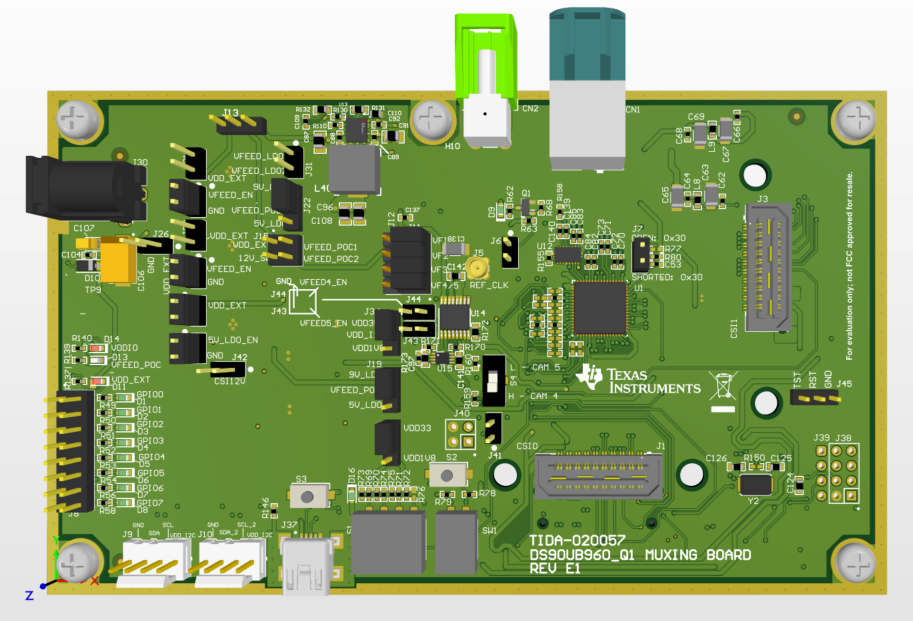
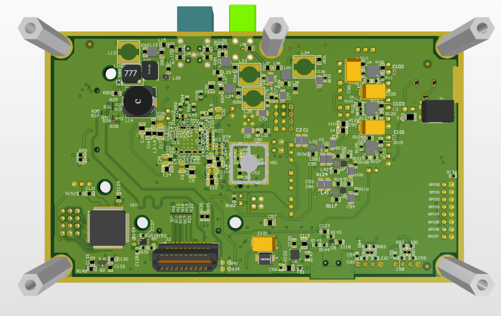
The setup for multiplexing with the previously-mentioned FPD-Link is executed as follows. A DS90UB960-Q1 EVM was modified with multiplexing capabilities on one out of four channels using a high-speed, bidirectional multiplexer, HD3SS3212-Q1. DS90UB960-Q1 is a quad 2MP camera hub FPD-Link III deserializer device with dual CSI-2 output ports. HD3SS3212-Q1 is a two-channel differential 2:1 and 1:2 multiplexing and demultiplexing device that operates at up to 10Gbps. A single mini-FAKRA connector was added in addition to the quad FAKRA connector for the additional fifth camera input. For implementing the multi-camera application in Vision Apps, five TIDA-02002 modules using an IMX390 imager were used in conjunction with this board. Figure 3-1 and Figure 3-2 show the layout for this board.
 Figure 3-1 Multiplexing Board Layout - Top View
 Figure 3-2 Multiplexing Board Layout - Bottom
The MUX board has a SAMTEC CSI-2 connector that interfaces with a TDA4VM (J721EXSOMG01EVM) SOM board mounted on the J721EXCPXEVM common processor board for Jacinto 7 processors. The interface with the TDA4VM allows for camera output to be seen on a connected monitor. To switch between cameras, switching protocol functionality must be added to the TDA4 in the Software Development Kit (SDK).