SNLU224D September 2017 – February 2023 DS90UB953-Q1 , DS90UB953A-Q1
- Trademarks
- 1Introduction
- 2Quick Start Guide
-
3Troubleshooting
- 3.1 Default Addresses
- 3.2 USB2ANY
- 3.3 ALP Software Setup
- 3.4
Troubleshooting ALP Software
- 3.4.1 ALP Loads the Incorrect Profile
- 3.4.2 ALP Does Not Detect the EVM
- 3.4.3 Error When Opening ALP: One Instance of this Application Can Be Active
- 3.4.4 Error Referring to USB2ANY Firmware Update
- 3.4.5 Identifying USB IDs and Corresponding Devices
- 3.4.6 Set up File for Loading Scripts and Create Buttons for Each Script
- 3.5 Additional Troubleshooting – Step-by-Step Guide
- 4Bill of Materials
- 5PCB Schematics
- 6Board Layout
- 7Related Documentation
- 8Revision History
3.5.3 Procedure
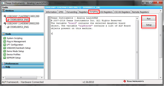
- Open the DS90UB954 (or variant) device window by
double clicking the profile and selecting to the
scripting tab as shown in #X645.
 Figure 3-36 Navigating to DS90UB954 (or
variant) Scripting Tab in ALP
 - If you would like to set up a file that loads all of the scripts and creates a button for running each script, consult GUID-9984C171-9F03-42EA-A760-106B1A046720.html. Otherwise, you can run scripts by clicking the Run button and navigating to their file location.
- If you would like to place the scripts in the default ALP script folder, move them to the file location:
C:\Program Files (x86)\Texas Instruments\Analog LaunchPAD 1.56.0010
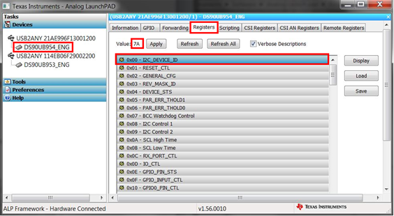
- Verify there is successful local I2C
communication that the script worked by going to
the register tab, selecting register 0x00 labeled
I2C_DEVICE_ID, and reading the value as shown in
#X1849. If the value is not 0x7A, then the correct
profile has not been assigned to the correct
USB2ANY ID. Consult GUID-07AAB36E-F8DD-4B1E-B31A-5FF887F5F39C.html#GUID-07AAB36E-F8DD-4B1E-B31A-5FF887F5F39C for more information.
 Figure 3-37 Reading I2C Device ID Within
the Register Tab
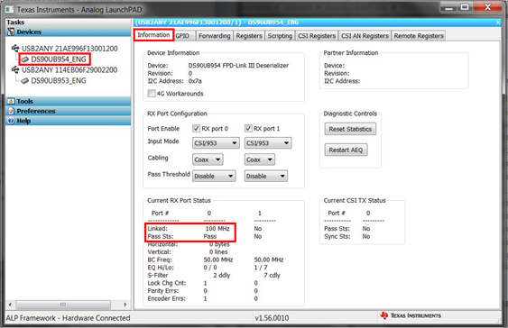
 - Ensure that the devices are setup properly by
checking that Pass Sts: displays Pass and Linked
has a frequency listed like shown in #X2902. In addition, be sure that D3, labeled Lock,
and D15 label Pass, are illuminated on the
DS90UB954EVM (or variant).
 Figure 3-38 Verifying Pass and Lock for
DS90UB954 (or variant) in ALP
 - Navigate back to the Scripting tab of the DS90UB954 (or variant) ALP profile and run the 953to954_patgen_YUV_1920x1080p-4Lanes-Working.py script to initialize a pattern generation from 953->954. The script may be found by clicking on the "Run PreDef Script" button. If the DS90UB954-Q1 (or variant) is not using an I2C address of 0x7A (8-bit form), the script should be modified to use the correct I2C address.
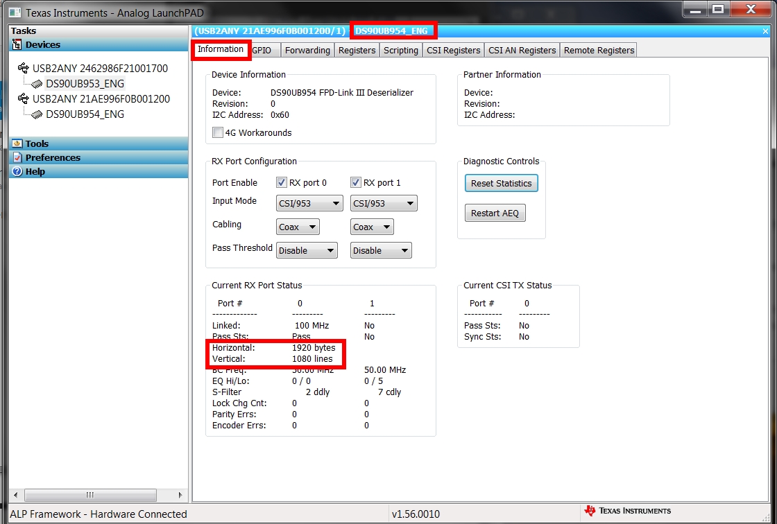
- Verify that the pattern
has been enabled navigating to the information tab
on the DS90UB954 (or variant), and checking to the
horizontal and vertical parameters for the
appropriate resolution defined by the camera.
#X925 shows 3840 bytes and 1080 lines for the
horizontal and vertical parameters, respectively.
Also, verify that the DC power supply, the HP
E3610, is sourcing more current.
 Figure 3-39 Verifying Camera
Initialization in ALP