SNVA790A October 2020 – July 2022 LMR36520
4.3 Load Transient
Load transient performance is a typical way of gauging the performance of a converter. The primary output of the Fly-Buck™ converter shows nearly identical load transient performance to that of a typical non-isolated buck with the same operating conditions. The secondary output load transient performance, however, is worse than that of the primary output because the control loop of the converter does not sense the secondary output voltage and therefore does not respond to changes in it. This means that the secondary output voltage will take longer than the primary output voltage to recover from the same load transient.
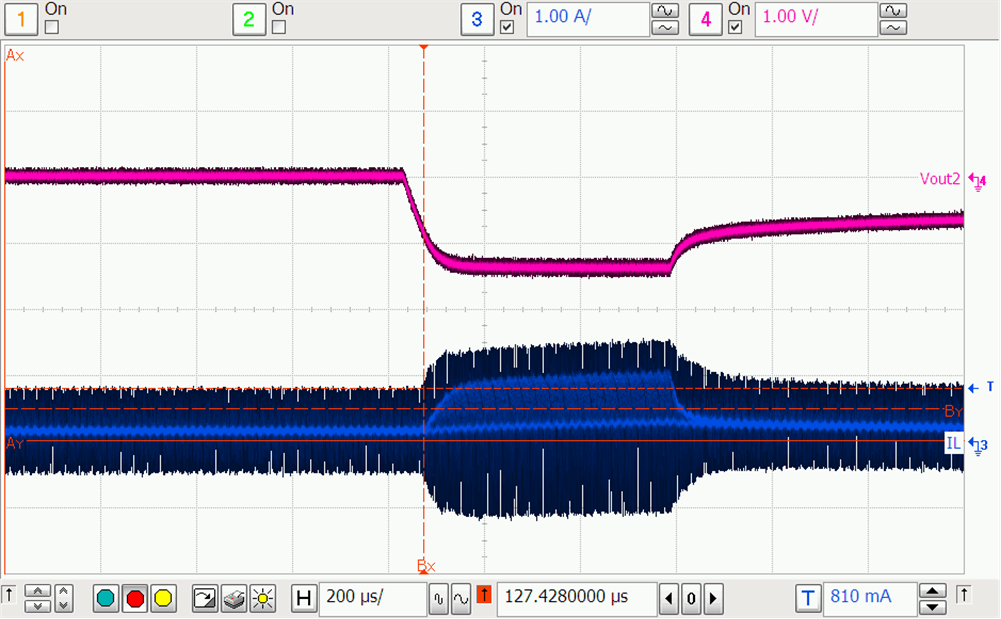
Figure 4-6 is the secondary output load transient while the primary output current equals 500 mA and the secondary load is stepped from 0 to 500 mA.
 Figure 4-6 12 VIN, 500 mA1, 0
to 500 mA2 Load Transient
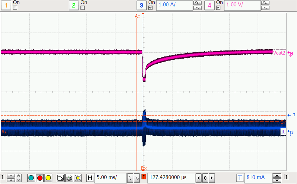
 Figure 4-7 shows a zoomed out image of Figure 4-6. It takes the secondary output voltage almost 10 ms to return to within 5% of its desired output voltage.
 Figure 4-7 12 VIN, 500 mA1, 0
to 500 mA2 Load Transient Zoomed Out