SPRACV2 November 2020 AWR1843 , AWR2243
- Trademarks
- 1Introduction
- 2Cascade Incoherence Sources and Mitigation Strategies
-
3Enabling Cascade Coherence and Improved Phase
Performance
- 3.1 High-Level Summary
- 3.2 Saving RF INIT Calibration Results at Customer Factory
- 3.3 Corner Reflector-Based Offsets Measurement at Customer Factory
- 3.4 Restoring Customer Calibration Results In-Field
- 3.5
Host-Based Temperature Calibrations
In-Field
- 3.5.1 Disabling AWR Devices’ Autonomous Run Time Calibrations
- 3.5.2 Enabling Host-Based Temperature Calibrations of Inter-Channel Imbalances
- 3.5.3 Switching of DSP Imbalance Data
- 3.5.4
Enabling TX Phase Shifter’s Host-Based
Temperature Calibrations
- 3.5.4.1 Estimating TX Phase Shift Values at Any Temperature
- 3.5.4.2 Temperature Correction LUTs for AWR1843TX Phase Shifter
- 3.5.4.3 Temperature Correction LUTs for AWR2243 TX Phase Shifter
- 3.5.4.4 Restoring TX Phase Shift Values – Format Conversion
- 3.5.4.5 Restoring TX Phase Shift Values – Transition Timing and Constraints
- 3.5.4.6 Typical Post-Calibration TX Phase Shifter Accuracies
- 3.5.4.7 Correcting for Temperature Drift While Sweeping Across Phase Settings
- 3.5.4.8 Amplitude Stability Across Phase Shifter Settings
- 3.5.4.9 Impact of Customer PCB’s 20-GHz Sync Path Attenuation on TX Phase Shifters
- 3.5.5 Ambient and Device Temperatures
- 4Concept Illustrations
- 5Miscellaneous (Interference, Gain Variation, Sampling Jitter)
- 6Conclusion
- A Appendix
3.5.2 Enabling Host-Based Temperature Calibrations of Inter-Channel Imbalances
The host must monitor the device temperatures and, when needed, change the analog configurations in the AWR devices to mitigate temperature drift effects. The following steps illustrate the procedure.
- Reading device temperature: use the AWR devices’ temperature sensors to measure
device temperatures. Use an average of all analog (TX, RX, CLK) temperature
sensors in all devices to determine a single average temperature. The relevant
APIs for temperature measurement are as follows:
- AWR RF TEMPERATURE GET SB (it can be used as an on-demand temperature sensor reading and is useful before the first frame starts).
- AWR MONITOR TEMPERATURE CONF SB (it can be used to pre-configure periodic temperature monitor reports).
- Determining bias setting: determine which bias setting (Low Bias, Mid Bias, or High Bias) to use for the sensor using the average temperature and the host’s knowledge of temperature trends (increasing or decreasing and expected long term temperature range).
- Configuring TX, RX, and LO codes: based on the selected bias setting, configure
TX, RX, and LO codes as follows:
- For AWR1243, AWR1843, AWR1642: Set TX and RX gain codes stored in the non-volatile memory for the selected bias setting using AWR TX GAIN TEMPLUT SET SB API and AWR RX GAIN TEMPLUT SET SB API, respectively. The codes must be set to the same value for all the temperature bins (–40C to –30C, –30C to –20C, –20C to –10C … 120C to 130C, 130C to 140C) in both APIs, and the codes may be different for different devices.
- For AWR2243: Override the temperature index corresponding to the selected bias setting for TX, RX, and LO DIST by issuing AWR RUN TIME CALIBRATION CONF AND TRIGGER.
- Before the first radar frame: the host must execute the above procedure before triggering the first radar frame after RF INIT.
- Transition timings and API sequences: after RF INIT, even after the frames have
started, the host must continually monitor device temperatures and identify if
bias setting transitions are needed. When needed, it must execute the above
procedure, with timing constraints.
- For the AWR1243, AWR1843,
and AWR1642, the timing constraints are as follows:
- The above SET APIs must be issued to all devices in the cascade in tandem and when no frames/chirps are ongoing.
- For this, AWR FRAMESTARTSTOP CONF SB API (stop) should first be issued to all the devices. The SET APIs must be then issued. The frames can then be resumed using AWR FRAMESTARTSTOP CONF SB API (start).
- The devices, upon receiving this API message, complete the ongoing radar frames before stopping further frames.
- For AWR2243, AWR RUN TIME CALIBRATION CONF AND TRIGGER SB can be issued
with appropriate temperature index override, even when frames are
running. The host must observe the following timing constraints to
ensure all the devices in the cascade honor and apply the necessary
adjustments at the same frame and avoid any intermittent inter-device
mismatches:
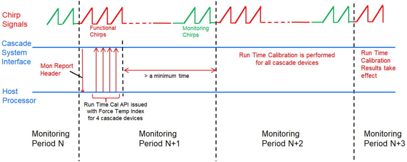
- The host should wait for monitoring report header API message corresponding to a monitoring period (say, monitoring period N). The message indicates that the previous monitoring period has ended and the next one is beginning.
- The host should then issue AWR RUN TIME CALIBRATION CONF AND TRIGGER SB and ensure that it reaches all the cascade devices in the same monitoring period, i.e. monitoring period N+1. The host should ensure that the cascade devices receive the new API before the next monitoring period (i.e. monitoring period N+2) begins (approximately a millisecond or earlier).
- The devices perform necessary computations related to the calibration adjustments in the next monitoring period (i.e. monitoring period N+2). The new calibration adjusted settings take effect in the subsequent monitoring period (i.e. monitoring period N+3). The timing is illustrated in Figure 3-2.
- For the AWR1243, AWR1843,
and AWR1642, the timing constraints are as follows:
- Transition temperature: the bias setting transitions are recommended to be near
the factory calibration temperature. This can be done by appropriate choice of
the temperature ranges for Low Bias, Mid Bias, and High Bias.
- Altering the TX, RX and LO DIST codes will cause phase jumps. These are expected to be compensated by DSP post processing (explained in later sections).
- To minimize the residual phase jumps after DSP post compensation, the jump magnitudes in the field must match those measured at factory. For this, the transitions are recommended when the temperature is as close as possible to the factory calibration temperature (typically the middle of Mid).
 Figure 3-2 AWR2243 RunTime Cal Temp Index Forcing Timing Diagram