SPRADD9 September 2023 TMS320F2800132 , TMS320F2800133 , TMS320F2800135 , TMS320F2800137 , TMS320F2800152-Q1 , TMS320F2800153-Q1 , TMS320F2800154-Q1 , TMS320F2800155 , TMS320F2800155-Q1 , TMS320F2800156-Q1 , TMS320F2800157 , TMS320F2800157-Q1 , TMS320F280021 , TMS320F280021-Q1 , TMS320F280023 , TMS320F280023-Q1 , TMS320F280023C , TMS320F280025 , TMS320F280025-Q1 , TMS320F280025C , TMS320F280025C-Q1 , TMS320F280033 , TMS320F280034 , TMS320F280034-Q1 , TMS320F280036-Q1 , TMS320F280036C-Q1 , TMS320F280037 , TMS320F280037-Q1 , TMS320F280037C , TMS320F280037C-Q1 , TMS320F280038-Q1 , TMS320F280038C-Q1 , TMS320F280039 , TMS320F280039-Q1 , TMS320F280039C , TMS320F280039C-Q1 , TMS320F280040-Q1 , TMS320F280040C-Q1 , TMS320F280041 , TMS320F280041-Q1 , TMS320F280041C , TMS320F280041C-Q1 , TMS320F280045 , TMS320F280048-Q1 , TMS320F280048C-Q1 , TMS320F280049 , TMS320F280049-Q1 , TMS320F280049C , TMS320F280049C-Q1
1.1 Cycle by Cycle (CBC) Protection
When PFC runs into overload conditions, for example, during AC voltage transient from high line to low line, or some fault events occur, it is required to implement overcurrent protection with CBC based PWM shut down control, in order to limit the PFC inductor current instead of shutting down the power stage. Normally, it is common to configure both PWM output for Q1 and Q2 to turn off together as soon as the inductor current reaches the overcurrent threshold. However, it might induce the risk for the power stage, especially during high temperature.
Because of the reverse recovery issue, a regular MOSFET cannot be used in a continuous-conduction mode (CCM) totem-pole PFC, so Q1 and Q2 need to be GaN or SiC FETs. As discussed in the third quadrant operation of GaN, located in Does GaN Have a Body Diode? - Understanding the Third Quadrant Operation of GaN, the reverse conduction voltage Vsd is much higher under third quadrant operation, ranging from 3 V~5 V, or even more with larger reverse current, which also applies for SiC. The high reverse conduction voltage can cause excessive losses, and it brings concerns on device’s thermal limitation and system reliability. Take positive cycle operation as example, showed in Figure 1-2, with the traditional PWM configurations, after both high side and low side FETs shut down at overcurrent event, large inductor current will continue to flow on the high side FET, so the conduction loss increases due to the third quadrant operation, which might cause the junction temperature rise up and lead to thermal damage for the GaN or SiC.
 Figure 1-2 PWM Configurations for Traditional
CBC Protection
Figure 1-2 PWM Configurations for Traditional
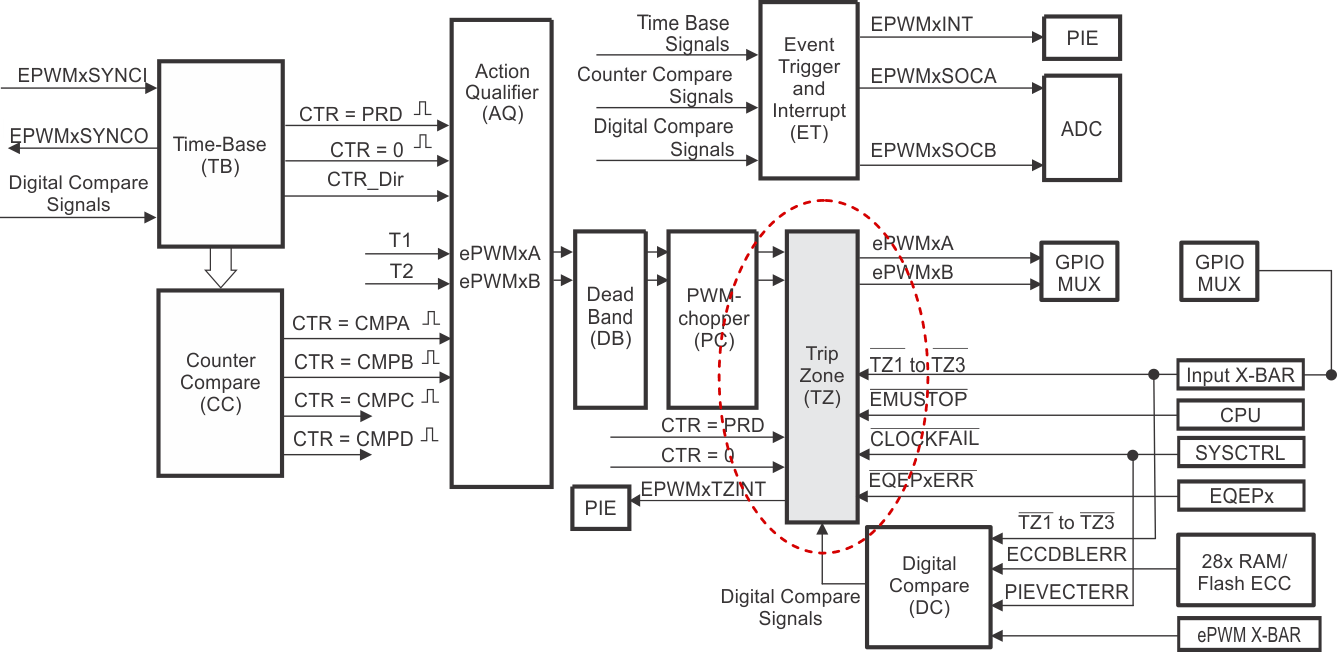
CBC ProtectionTherefore, an ideal CBC protection scheme for the PWM configurations is shown in Figure 1-3. The PWM for the sync switch (high side FET Q1 for positive cycle in this case) should be turned on after the active switch turns off, with a customized dead time. However, the traditional trip-zone (TZ) submodule of ePWM could not be used to achieve the above logic. As shown in Figure 1-4, when a cycle-by-cycle trip event occurs, the action specified in the TZ submodule is carried out immediately on the ePWMxA and ePWMxB outputs, without any delay, since the TZ submodule is the last part before the ePWM outputs. In addition, for totem pole PFC, the ePWM output used for active FET and sync FET is different based on the VAC polarity, so the actions set inside the TZ submodule could not work for both positive and negative cycle automatically.
 Figure 1-3 PWM Configurations for Ideal CBC
Protection
 Figure 1-4 ePWM Submodules