SSZT777 march 2018 FDC2214
The accumulation of frost or ice on an evaporator coil always presents a challenge in home appliances such as refrigerators, freezers and air conditioners. The accumulation of frost or ice insulates the air circulating through the evaporator unit, which makes maintaining the overall temperature difficult. Also, atmospheric conditions that lead to the formation of ice block the heat exchange: the thicker the frost, the worse the efficiency. Figure 1 shows an efficiency comparison with different frost thicknesses based on one model of refrigerator.
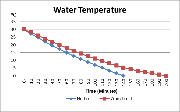 Figure 1 Comparison by Cooling Down a
Fixed Amount of Water
Figure 1 Comparison by Cooling Down a
Fixed Amount of WaterCurrent Solutions
Solving these problems requires a defrosting system that is operatively associated with the heat exchanger. The question is when to activate the defrost cycle. One easily implemented method is to include a clock, which at some pre-selected interval shuts the compressor off and turns on a thermal heating device adjacent to the evaporator coils, melting the frost or ice. Another popular method uses temperature-sensitive devices such as a negative temperature coefficient (NTC) thermistor to measure the temperature of the refrigerating medium as one parameter. The disadvantage of these methods is that frost or ice does not always accumulate at a constant rate, depending on the ambient humidity and air temperature. Defrosting on a regular time cycle, whether necessary or not, is inefficient and wastes electrical power.
Frost or Ice Detection Based on Capacitive Sensing
Capacitive sensing enables a more reliable solution for measuring the thickness of frost or ice. The Texas Instruments (TI) Capacitive Frost or Ice Detection Reference Design, Resolution of <1mm, Temperature Drive <0.25% detects the amount of frost and ice accumulated on the surface of a cooling body using capacitive-sensing technology. The capacitance of a sensor changes according to the thickness of frost or ice because of the variation of the dielectric constant between air and frost or ice. Let me explain the basic principles.
where C is the capacitance related by the stored charge, Q, at a given voltage, V.
The capacitance (measured in farads) of a parallel plate capacitor (see Figure 2) consists of two conductor plates and is calculated using Equation 2:
where A is the area of the two plates (in meters), is the dielectric constant of the material between the plates, is the permittivity of free space (8.85 × 10⁻¹² F/m) and d is the separation between the plates (in meters).
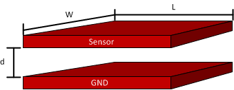 Figure 2 Parallel Plate
Capacitor
Figure 2 Parallel Plate
CapacitorCapacitive sensing is a technology based on capacitive coupling. A basic capacitive sensor is anything that is metal or a conductor and detects anything that is conductive or has a dielectric constant different from the air. Capacitance can be detected to sense different applications by changing one of the parameters while keeping the rest constant. Table 1 shows the dielectric constant of some materials.
| Material | Dielectic Constant (Ɛᵣ) | Comment |
|---|---|---|
| Air | 1 | - |
| Water | 80 | at 20°C |
| Glass | 7.6 to 8.0 | - |
| Paper | 2.3 | - |
| Ice | 3.2 | - |
The accumulation of frost and ice on the surface of a cooling body causes the capacitance between two parallel plates (the metal surface of the cooling body and a specifically designed sensor) to change due to the equivalent dielectric constant change, as shown in Figure 3. When a properly designed sensor composed of a conducted material is fixed on the surface of a cooling body, the parameters for d, and A remain constant. The capacitance will be a function of the equivalence of, which is the basic principle of frost and ice detection.
 Figure 3 Model for Frost and Ice
Detection Based on Capacitance
Figure 3 Model for Frost and Ice
Detection Based on CapacitanceTable 1 shows that the dielectric constant of ice is three times greater than that of air and the dielectric constant of water is up to 80 times greater. When ice or water is positioned between the parallel plate capacitor, the capacitance increases with the thickness.
Figure 4 shows an example of the expected capacitance change curve based on a copper mesh sensor. In Stage 1, the capacitance remains a constant value when there is no frost or ice on the dry surface of a cooling body. At the beginning of Stage 2, the refrigerator or air-conditioner compressor starts to work and frost or ice accumulates on the surface of the cooling body. Due to the dielectric constant change from air to ice (see Table 1), the capacitance increases based on the thickness of the frost or ice. The defrost cycle activates when the desired thickness has been detected. The capacitance experiences a sharp change when ice (= 3.2) turns to water (= 80), shown in Stage 3, and then returns back to the original value after the water drops from the cooling body.
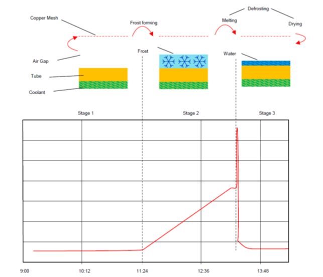 Figure 4 Capacitance Change in
Principle
Figure 4 Capacitance Change in
PrincipleTest Results
I built a test platform based on a refrigerator. Figure 5 shows the frost formation process on the surface of the evaporator, and Figure 6 shows the capacitance-change curve during one cycle. The six pictures labeled in Figure 5 correspond to the six points, also labeled, in the curve of Figure 6. This system uses capacitance values to calculate the amount of frost.
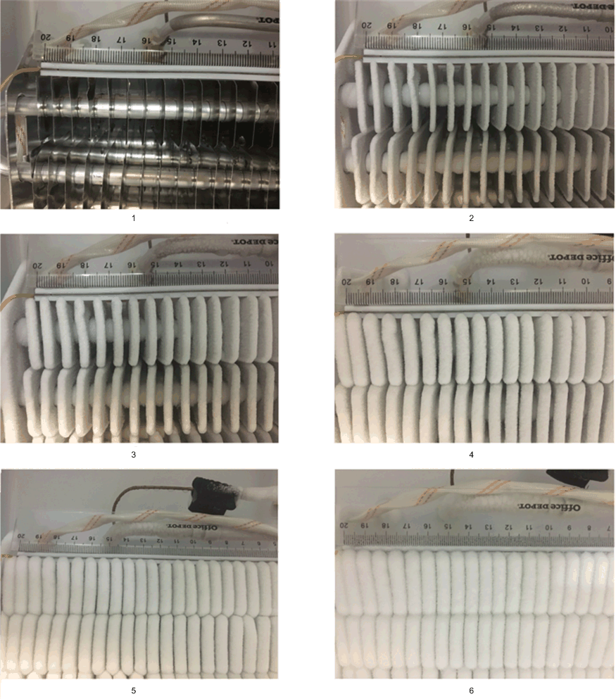 Figure 5 Frost Formation
Process
 Figure 6 Sensed Capacitance During the
Frost Formation Process
Figure 6 Sensed Capacitance During the
Frost Formation ProcessTo measure the capacitance, I used TI’s FDC2214, which is a high-resolution capacitive-to-digital converter. The devices employ an innovative narrow-band based architecture to offer high rejection of noise and interferers while providing high resolution at high speed. The test results verify that this is a robust and cost effective solution which could solve the problem of frost or ice detection in refrigeration system and significantly improve the system efficiency. Using relative values rather than absolute values of capacitance is a good way to improve the system reliability even under complex environmental conditions.
Sensor Placement Recommendations
Two options are proposed for the placement of sensors.
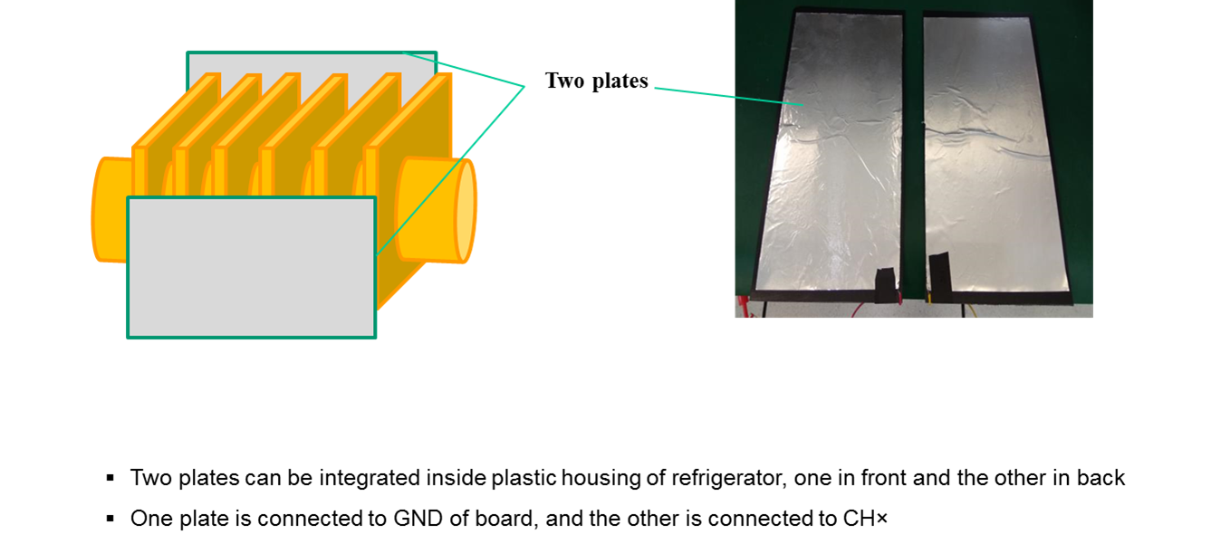 Figure 7 Two Plate Sensor Model
The conductive plates are recommended to integrate inside the plastic housing of evaporator, which is shown in Figure 8.
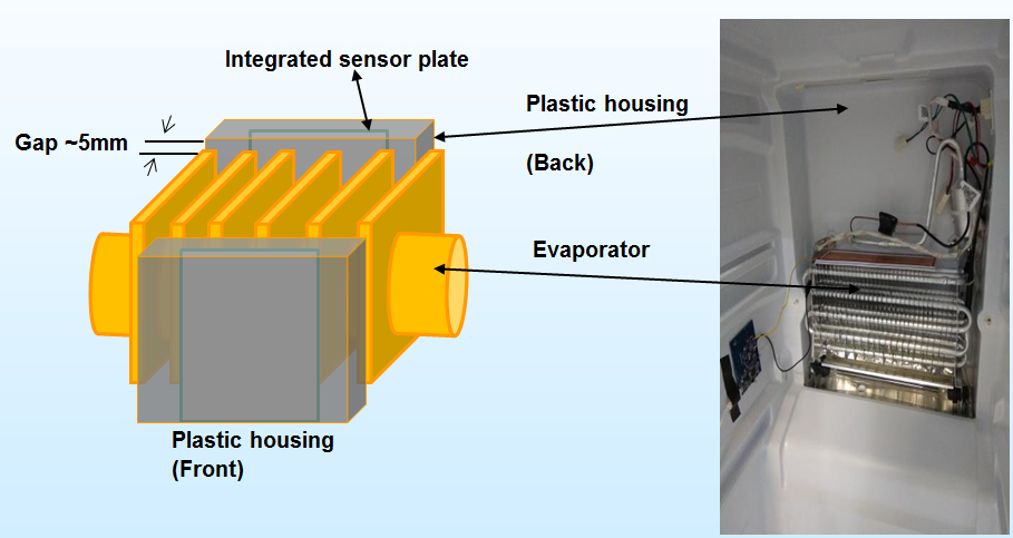 Figure 8 Two Plate Sensor
Installation
Figure 8 Two Plate Sensor
InstallationAs is shown in Figure 8, the two conductive plates are recommended to place inside the plastic housing (one in front and one in back) of evaporator so that air flow will not be affected.
Option 2 (Preferred): Take the evaporator as one plate of sensors. In this option shown in Figure 9, only one external conductive plate is needed which lowers cost. Due to safety consideration and ESD protection in some cases, an external safety capacitor (e.g. Y capacitor, 1nF) is added in series with the sensor instead of in parallel.
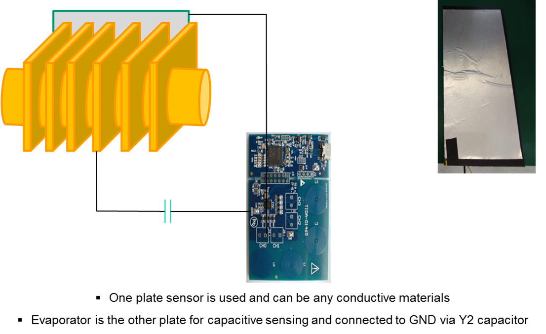 Figure 9 Single Plate Sensor
Model
Figure 9 Single Plate Sensor
ModelIn the instance when only one plate is used, it is easy to integrate inside the plastic housing of evaporator, which is shown in figure 10. The air gap between the evaporator and sensing plate depends on the required defrost thickness and is often times around 4mm-10mm.
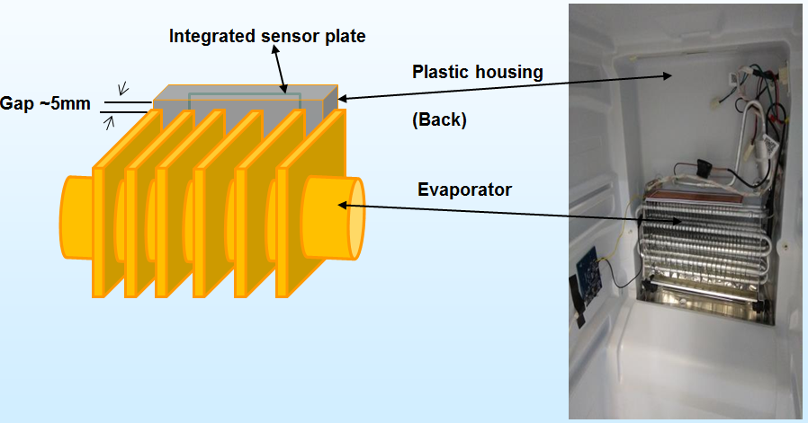 Figure 10 Single Plate Sensor
Installation
Figure 10 Single Plate Sensor
InstallationAdditional resources
- Find the best solutions for your next-generation appliance designs.