SSZT972 august 2017 ISOW7841
“Emissions Impossible”! Emissions are inevitable when it comes to switching circuits. With circuits that have an external transformer for isolated power, you can increase the size of the transformer to proportionately reduce the switching frequency and thereby reduce the switching noise that causes emissions. But you cannot eliminate this noise completely. In my last post, “Small doesn’t mean you compromise performance,” I discussed the benefits of an integrated solution that provides better performance compared to a discrete solution. Including a transformer in the integrated solution has its advantages, but it also puts an additional burden on emissions performance.
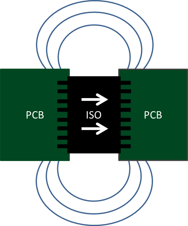
Let me elaborate. When integrating the isolation transformer inside the chip, the size and turns of the transformer are minimized so as to keep the die size reasonable. For the same power transfer, this increases the switching frequency, which results in higher emissions. Figure 1 shows how data and power transmission from the left side to the right side happens through the isolation barrier using a high-frequency carrier. The isolating device connects to two sides of the printed circuit board (PCB), forming a dipole antenna. Since the high-frequency carrier is generated and passed through the isolating device, the formed dipole antenna radiates energy. The radiations are perpendicular to the direction of the dipole.
 Figure 1 Creation of a Dipole in an
Isolated System
Figure 1 Creation of a Dipole in an
Isolated SystemThese radiations not only affect the signal integrity of the isolation output but also interfere with adjacent signals and cause data corruption, ultimately leading to system failures in some cases. So it is important to keep the radiations as low as possible. Standards vary depending on applications, but Comité International Spécial des Perturbations Radioélectriques (CISPR) 22 is the most common standard used in industrial applications. TI has used this standard to compare the performance of different solutions.
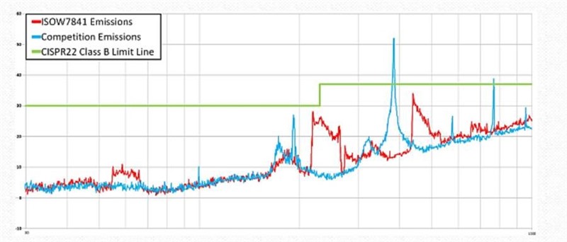
Figure 2 shows the radiated emissions comparison of TI’s ISOW7841 integrated isolated signal and power solution with a similar device on the market. TI tested both devices on the same evaluation board with identical load conditions. With careful circuit design and clock management, the ISOW7841 passes CISPR Class B standards, while the competitor’s device fails.
 Figure 2 Radiated Emissions of the
ISOW7841 and a Competitor’s Device at a 5V Input and 80mA Load
Figure 2 Radiated Emissions of the
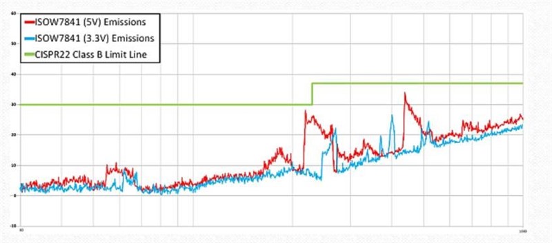
ISOW7841 and a Competitor’s Device at a 5V Input and 80mA LoadOne way to further reduce emissions is by reducing the power-supply voltage. If there is any flexibility between 3.3V or 5V power supplies, using a 3.3V supply reduces the slew rate of DC/DC converters, thereby reducing emissions, as shown in Figure 3.
 Figure 3 ISOW7841 Radiated Emissions at
5V and 3.3V Inputs
Figure 3 ISOW7841 Radiated Emissions at
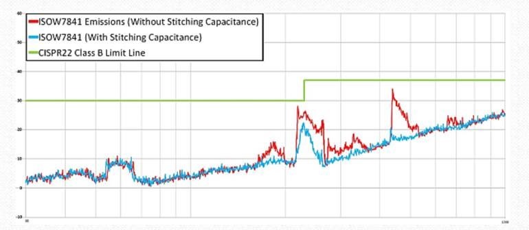
5V and 3.3V InputsAnother common method of reducing emissions is adding a stitching capacitor between the left and right side of the isolated board. Figure 4 depicts scenarios where the stitching capacitor is present and absent across the isolator. This stitching capacitor may be a physical capacitor added on the board or included in the board design by using the GND and VCC planes of the board to build it internally. The application note, “Low-Emission Designs With ISOW7841 Integrated Signal and Power Isolator,” has more details about stitching capacitor design guidelines.
 Figure 4 The ISOW7841 with and without
a 30pF Stitching Capacitance at a 5V Input and 80mA Load Current
Figure 4 The ISOW7841 with and without
a 30pF Stitching Capacitance at a 5V Input and 80mA Load CurrentControlling radiated emissions is important to overall system performance, thereby making device selection with low emissions critical. The ISOW7841, with its simple board design changes, enables you to achieve the right emissions performance. If you have questions regarding board schematics or layout reviews, post a question in the TI E2E™ Community Isolation forum.
Additional Resources
- Check out the ISOW7841 data sheet.
- View the video, “Reinforced Isolation and Power: An Integration Story.”
- See TI’s entire isolation portfolio.