SSZTAF4 february 2017 TPSM84A21 , TPSM84A22
I’m sure at some point or another, we’ve all agreed to terms and conditions that we haven’t really read. Why bother spending so much time reading fine print? Like any important document, data sheets also have fine print – one page of flashy specs, but upwards of 20 pages of fine print. This is especially true for power modules, where integration can mask key details about the device. There are a few common stumbling blocks in evaluating power modules based on the front page of their data sheet that I’ll discuss in this blog series.
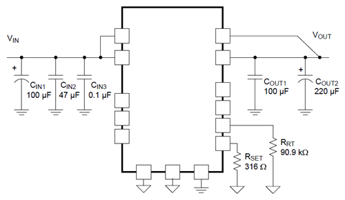
It can be challenging to evaluate how integrated a module is. At its most basic level, a power module is just a small component with a converter and inductor inside, essentially replacing some amount of the board design that a power engineer would have to put time and effort into creating. However, not all modules are created equal: just because you’re using a power module doesn’t mean that you won’t also need external components (in some cases, like in Figure 1, a lot of them).
 Figure 1 Input and Output Capacitors
Add Complexity to Module Circuits
Figure 1 Input and Output Capacitors
Add Complexity to Module CircuitsThe greatest variance among modules has to do with whether the input and output capacitors are integrated or whether you have to add them externally. Even in modules with integrated capacitors, it’s critical to delve further into the data sheet to identify just what capacitance is inside your module. In some cases, the output capacitors included in the module are like a “donut” spare tire: while technically functional, they’re not really designed to work full time. A good way to identify whether you’ll need more capacitance is to look at the performance curves in the data sheet: if the manufacturer wasn’t able to achieve those results without adding external capacitors to the circuit, it’s likely you won’t be able to either. Modules like TI’s TPSM84A22 are good options, because even the specs on the front page are pulled without using external components.
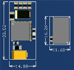
External components also play heavily into the size of a power module solution. Module manufacturers all want to tout “the smallest footprint” or “lowest profile,” but you need the whole story for these claims to be meaningful. For example, a module with a 9mm-by-15mm footprint sounds considerably worse than a module with a 10mm-by-10mm footprint, but once you add the necessary capacitors to the 10mm-by-10 mm module, you may find it takes up much more space on the board. This principle is illustrated in Figure 2 below. For this reason, it’s important to look beyond just the module package size to determine what’s the best fit for your system.
 Figure 2 Module Solution Size Can Vary
Widely from Module Package Size
Figure 2 Module Solution Size Can Vary
Widely from Module Package SizeBe sure to read my other installment of this series, Designing with integrated DC/DC power modules: how to check switching frequency, transient performance and output capacitance, where I discuss evaluating module efficiency and transient response. Read more about power modules and learn more about TI’s power module offerings.