SSZTAN4 november 2016 LPV801 , LPV802 , LPV811 , LPV812
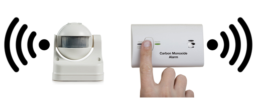
Designers of Internet of Things (IoT) applications have two primary concerns: managing power to maximize battery life and ensuring reliable operation against all sorts of electromagnetic interference (EMI). The IoT revolution will lead to the deployment of billions of battery- and line-powered connected devices, many of which will be wireless, all vying for the same spectrum of frequencies. This will create an increasingly noisy environment, with electromagnetic waves radiating from multiple sources. Interference from electromagnetic signals has been a problem of the shared unlicensed spectrum since the introduction of wireless devices, but the magnitude of the problem increases when the number of devices in operation multiplies. End equipment such as smoke detectors, toxic gas sensors and PIR sensors which have wireless capability need to be tested for additional radiation EMI tests because of their interactions with each other as shown in Figure 1.
 Figure 1 Passive Infrared (PIR) Sensor and Carbon Monoxide Detector with Electromagnetic Waves
The race to create wireless sensing nodes has brought in a degree of complexity to EMI testing. System designers need to carefully select components to avoid expensive redesigns that could delay time to market in the final stages of product development. In addition to working under noisy conditions, battery powered connected devices will also need to operate reliably for years without the need to change batteries. The battery life of IoT devices varies greatly, from hours to years, depending on the application and its operating environment. Designers of these IoT devices will have to choose components that consume very low current to extend operating life and offer EMI immunity.
TI’s LPV811 family of nanopower amplifiers consume quiescent current as low as 320nA to maximize battery life and are internally protected from EMI. These devices do not, however, include the full input EMI filter seen on many recently released operational amplifiers. We at TI did this intentionally, as adding an input EMI filter greatly increases the input capacitance, which can cause peaking in sub-microampere circuitry with large feedback resistor values and source impedances. Instead, we employed internal (proprietary) precautions in the layout and internal design of the LPV801, LPV802, LPV811 and LPV812 to make it as EMI-hardened as possible.
To verify the effectiveness of our built-in EMI mitigation technique, we compared the LPV802 against two popular competitive devices that do not have internal EMI protection. Under all conditions, the circuit using the LPV802 demonstrated better EMI immunity than circuits using competitive devices. We tested all three devices for EMI tolerance under IEC 61000-4-3 (Electromagnetic Compatibility (EMC) -radiated test conditions. We subjected the devices under test (DUT) to a calibrated radio frequency (RF) field over an 80MHz to 6GHz frequency range while monitoring the DUT for malfunctions in accordance with the IEC 61000-4-3 EMC-radiated specification. To compare the three devices, we exposed all three devices to the same EMC radiation at the same time in identical circuits and monitored their output for deviations. In addition, to gauge the effectiveness of a common EMI filtering technique, we tested two sets of boards. One set of boards had added external input EMI capacitors, and one set did not have EMI capacitors.
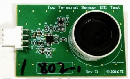
Figure 2 shows the test board built on a standard 62mil, two-layer FR4 board, with ground planes on both sides to test EMI performance. A four-pin connector enabled quick board changes. Socketing the sensor pins enabled easy removal of the sensor.
 Figure 2 Test Board with Sensor
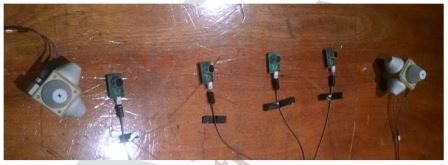
Figure 3 shows the test setup in the chamber. There were four boards for testing EMI performance. Three of the boards had identical circuitry, with different operational amplifiers mounted on them. One extra board was built in a ground-reference configuration but was not used in the test. We connected each of the four boards to a central battery box (2 x AA cells) through 1m of four conductor-shielded cables with EMI chokes on both ends. We connected the battery box to the control room via 15m of UTP CAT-5 cable, with appropriate EMI chokes, to deliver the output voltages to the logging system. The two white boxes with the cones are the field sensors for monitoring the field during the test.
 Figure 3 Test Setup for IEC61000-4-3 EMC-radiated Test
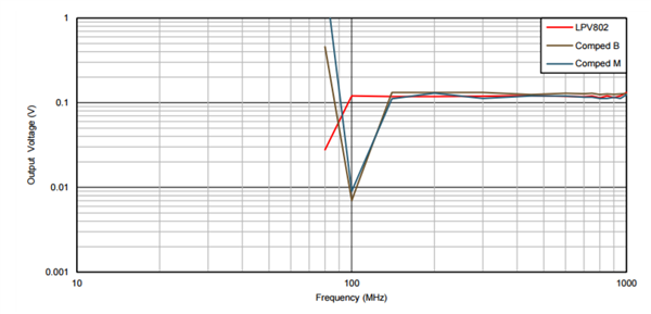
Figure 4 shows the results of one of the IEC 61000-4-3-prescribed tests. At 30V/m radiation levels, both competitive devices start failing at 140MHz, while the LPV802 held down to 100MHz. In general, the EMI performance of the circuit using the LPV802 was better than the circuits using competitive devices for all of the prescribed tests at different radiation levels, particularly in the 100-200MHz range. All of the devices were mostly unaffected by the upper (>400MHz) frequencies. For details regarding test conditions and results, refer to the application note, “Comparing EMI Performance of LPV802 with Other Devices in a Gas Sensor Application.”
 Figure 4 Results of 30V/m Test with Capacitor
Adding external EMI input capacitors also helped overall performance, and I recommend adding them as part of the normal design process. EMI protection does not completely eliminate the effects of EMI, but it does help reduce the effects.
Adding external filtering further reduces the effects, and I recommend external filtering even when using EMI-protected devices.
Using components like the LPV801, LPV802, LPV811 and LPV812 that consume nano-amperes of quiescent current and are EMI hardened helps designers to build systems that have longer battery life and that are compliant with worldwide EMI regulations. This helps reduce maintenance costs, improve time to market and eliminates the need to do expensive re-designs due to failure in EMI in the final stages of product development.
Additional Resources
- For complete test results at different conditions, please see the application note, “Precision Voltage Offset: When Does it Matter?”
- Download the LPV801, LPV802, LPV811 and LPV812 data sheets to learn more about the specific features of each device.
- Download the Micropower Electrochemical Gas Sensor Amplifier Reference Design.
- Download the Low Power Wireless PIR Motion Detector Reference Design Enabling 10 Year Coin Cell Battery Life reference design.
- Download the Low Power Carbon Monoxide Sensor with 10+ Year Coin Cell Battery Life reference design.