TIDA035 October 2020
3 Equation Verification by Simulation
Simulation can be used to verify that the analysis and the final equations are correct to get the right RISOP and RISON. The circuit itself is very simple and TINA simulation is a good choice here.
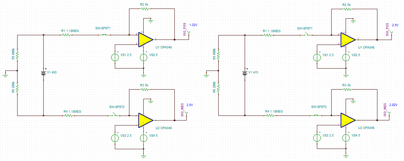
In this simulation, Rps = Rns = 1.18 MΩ, Rs1 = Rs2 = 5 kΩ. Assume the insulation resistances RISOP = 800 kΩ and RISON = 200 kΩ. When only S1 is closed, the battery voltage is 400 V and output ISO_POS is 1.32 V. When only S2 is closed, the battery voltage fluctuates up to 415 V and the corresponding output ISO_NEG is 2.82 V.
 Figure 3-1 TINA Simulation Results of Two
Scenarios
Figure 3-1 TINA Simulation Results of Two
Scenariosα equals to 280.98 based on Equation 3, and β is equal to -73.02 based on Equation 6. RISOP and RISON can be derived to 812 kΩ and 204 kΩ respectively according to Equation 8, which are very close to the simulation values.