SBAU419 November 2022 TMAG5170
4.1.3 Switch
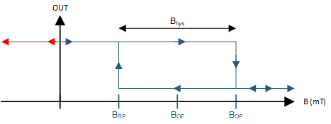
Switch type devices are typically offered in two varieties. Uni-polar sensors are sensitive to either a positive or negative field in the direction of sensitivity for the sensor. Whenever the input field exceeds the operating point threshold (BOP), the output toggles to the active state. Once in this state, the field must return below the release point threshold (BRP). If BOP and BRP were set at the same level of magnetic input, then the device may operate unpredictably due to mechanical vibration or electrical noise. To prevent this, some amount of hysteresis (BHYS) are typically included into the device design.
 Figure 4-3 Unipolar Switch Output
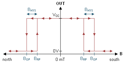
 Figure 4-4 Omnipolar Switch Output
Omnipolar switches operate similarly, however the key difference is that the output may toggle with either polarity of magnetic input. A major advantage for this device type is that the sensor can be agnostic to the orientation of the magnet. This means that the magnet may be installed quickly during product assembly.
When configuring a simulation to use a switch type device, the input fields will appear as shown in either #GUID-FDB6BA93-B332-4541-995D-0DD4AA2D824E or #GUID-AA7E6BB0-E0DF-454D-899B-CAB19A73C015.
To assist with design, radio buttons that allow the user to select minimum, typical, and maximum threshold values are enabled. While BHYS for any individual sensor should fall within the published limits in the device-specific data sheet, it can be helpful to design functionality around the worst case scenario. For this, it is typically recommended to check against BOP Max and BRP Min from the device-specific data sheet. These values must be selected for the simulation to run.