SBOA280A April 2018 – November 2023 ESD122 , ESD204 , ESD224 , ESD341 , TPD1E01B04-Q1 , TPD1E04U04 , TPD1E05U06 , TPD2E009 , TPD4E004 , TPD4E02B04 , TPD4E05U06 , TPD4E110 , TPD4S009
High-Definition Multimedia Interface (HDMI) remains one of the most popular interfaces for transmitting video and audio data since the creation of HDMI in 2002. With each HDMI standard update, improvements in process technology allow manufacturers to increase data bandwidth and add additional features in smaller and smaller chipsets. However, with decreased size, HDMI components become more sensitive to transient voltages such as electrostatic discharge. This creates a need for ESD protection that clamps at very low voltages without compromising high speed signal integrity.
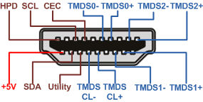 Figure 1 Pinout of the HDMI Receptacle
In the HDMI connector (Figure 1) there are four differential pairs of transmission minimized digital signaling (TMDS) channels. Three TMDS pairs (TMDS0, TMDS1 and TMDS2) are responsible for transferring millions of pixels of data per second for HDMI 2.0, while the TMDS CL pair provides the clocking signal to synchronize this information.
Apart from the four TMDS pairs, the HDMI connector has six other channels: The hot plug detect (HPD) channel, which senses when a connection is established, the consumer electronic control (CEC) channel, which allows users to control devices through HDMI, the utility channel, which is used for an HDMI Ethernet or audio return channel, the SDA and SCL channels, which provide I2C control, and the final channel, which provides 5 V of power.
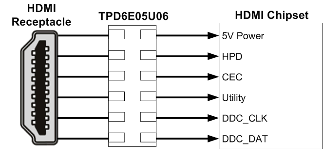
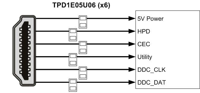
To protect against ESD failure, a 5-V working voltage, 6-channel TVS diode such as the TPD6E05U06 can be placed on the non-TMDS channels by the HDMI connector (5 V power, SDA, SCL, HPD, CEC and utility). 5-V working voltage, 1-channel TVS diodes (TPD1E05U06) also provide layout flexibility. Minimizing the capacitance of the diodes is usually not a concern since these non-TMDS channels do not pass high speed data,.
 |
 |
Alternatively, the TMDS channels pass differential data that can reach 18Gbps (6Gbps for each pair) for HDMI 2.0, with a maximum single-ended operating voltage of 3.3 V on each differential line. As a result, the ESD protection diodes placed on these high-speed traces require low enough capacitance to maintain signal integrity and meet the HDMI compliance standard.
Due to the sensitive nature of the TMDS I/O pins, clamping voltage must be minimized for TMDS ESD protection. This protection is accomplished by selecting an ESD diode with ultra-low dynamic resistance (RDYN). The diode provides a low impedance path to steer current away from sensitive circuitry downstream when an ESD strike is present.
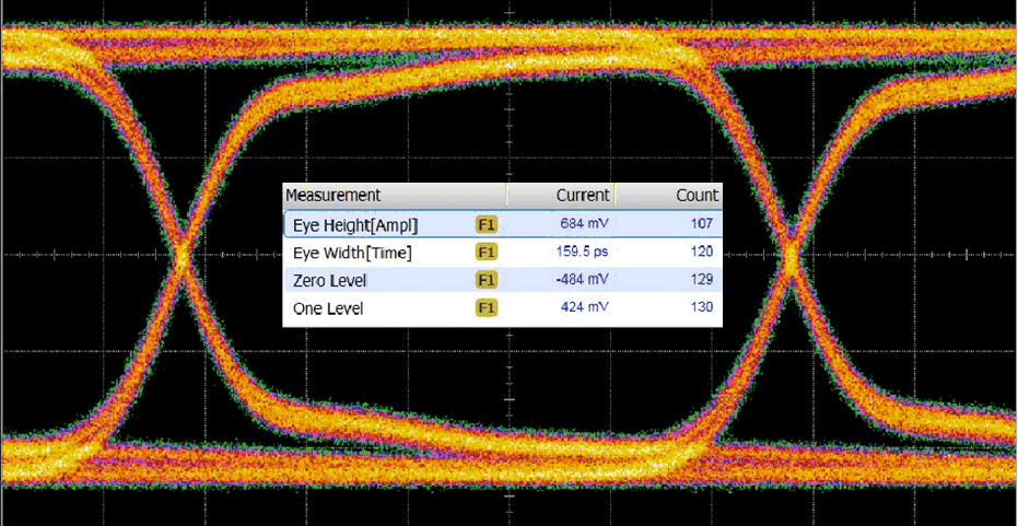
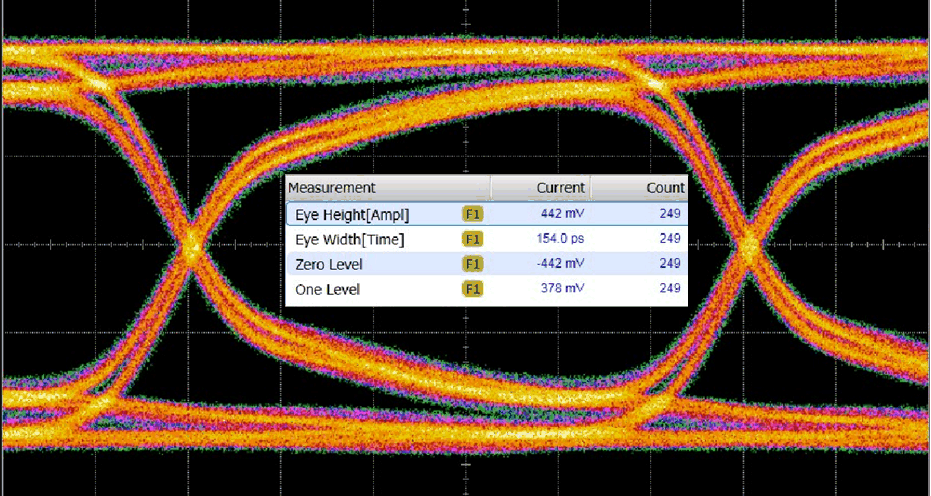
ESD RDYN and capacitance have an inverse relationship. Increasing the diode junction area decreases the RDYN but increases the diode capacitance which potentially degrades signal integrity. As a result, selecting TVS diodes that protect the TMDS channels without compromising the data transfer is challenging. However, the ESD224 is a 4-channel ESD protection device that is able to clamp ±8kV IEC ESD events to sufficient levels while maintaining an ultra-low capacitance by employing TI’s proprietary ESD process technology. Since there are four pairs of TMDS channels, two ESD224 protection diodes provide the necessary protection on TMDS traces while passing the signal integrity eye diagram mask test (Figure 3).
The ESD224 is capable of providing the necessary ESD clamping protection for sensitive HDMI 2.0 redrivers, retimers, and chipsets. For example, the BCM7250 is a Broadcom HDMI 2.0 SoC that fails at low transient voltages: 9.15 V and -5.71 V. In Figure 4, a 100 ns transmission line pulse (TLP) determines the ESD failure voltage since 100 ns is approximately the length of an IEC ESD pulse.
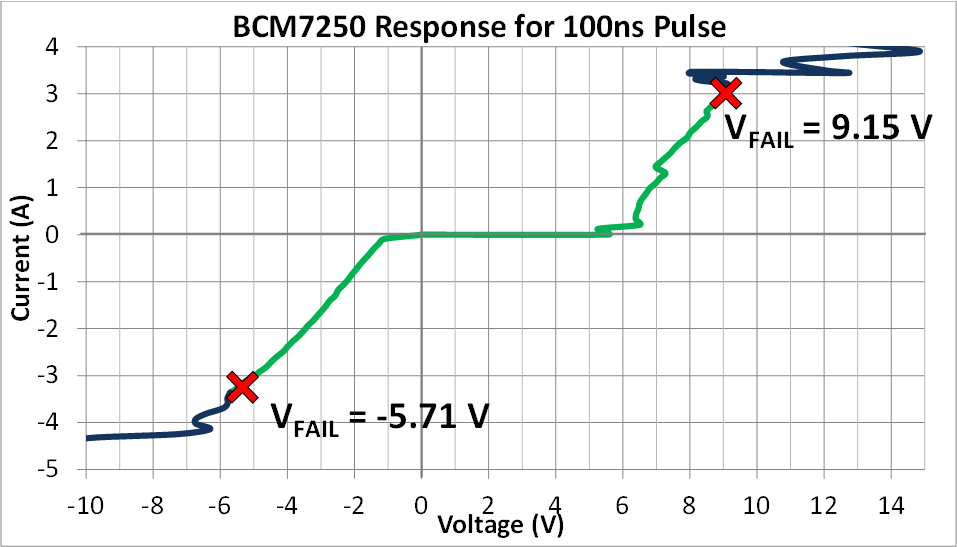 Figure 4 BCM7250 Fails at 9.15 V and -5.71 V
During ESD Events
Figure 4 BCM7250 Fails at 9.15 V and -5.71 V
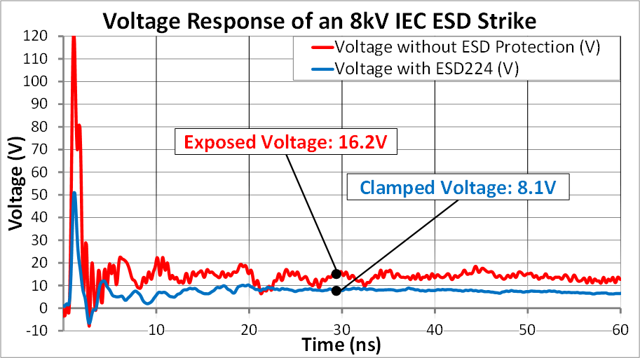
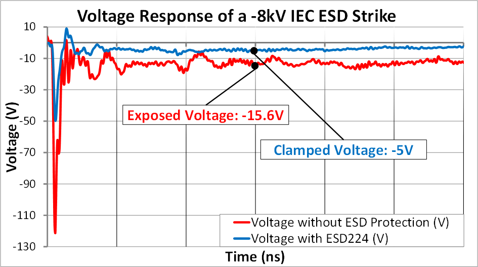
During ESD EventsThe TVS diode prevents the positive clamping voltage from exceeding 9.15 V and the negative clamping voltage from exceeding -5.71 V, which protects sensitive HDMI 2.0 SoCs, such as BCM7250, against ESD strikes. Figure 5 shows that the ESD224 provides this protection by clamping an 8-kV IEC ESD strike to 8.1 V and a -8-kV IEC ESD strike to -5 V.
For a complete HDMI 2.0 option, 2x ESD224 can protect the TMDS channels and 6x TPD1E05U06 can protect the other channels. If the ultra-low clamping performance of the ESD224 is not required, the TPD4E02B04 can protect the TMDS channels.
| Device | Optimized Parameters | Performance Trade-Off |
|---|---|---|
| TPD4E02B04 | 0.25 pF capacitance, flow through routing | Higher clamping voltage |
| TPD4E05U06 | 5 V working voltage, flow through routing | Higher clamping voltage |
| ESD204 | 30 kV/30 kV IEC rating, 5.5 A surge protection, flow through routing | Higher capacitance |
