SCPA062 July 2021 TCA9517
3 SDA Signal During Acknowledge With Propagation Delay (TCA9517 A to B)
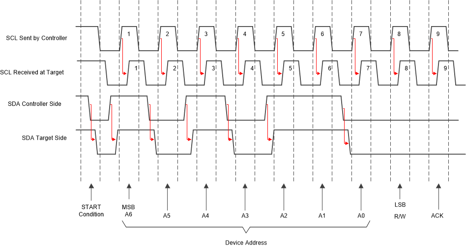
When the TCA9517 is added to the system for level translation or for redriving purposes, it introduces a propagation delay due to the integrated buffer design. Figure 3-1 shows an exaggerated timing diagram for the SCL and SDA lines with propagation delay added to the timing.
 Figure 3-1 I2C Timing With
Propagation Delays From I2C Buffer
Figure 3-1 I2C Timing With
Propagation Delays From I2C BufferFrom a data integrity standpoint, the signal delay does not impact the ability for the controller and target to communicate properly because the delay is equal for both the SCL and SDA lines. From a timing perspective, the SDA line remains stable for the entire portion of the SCL high period for the target device.
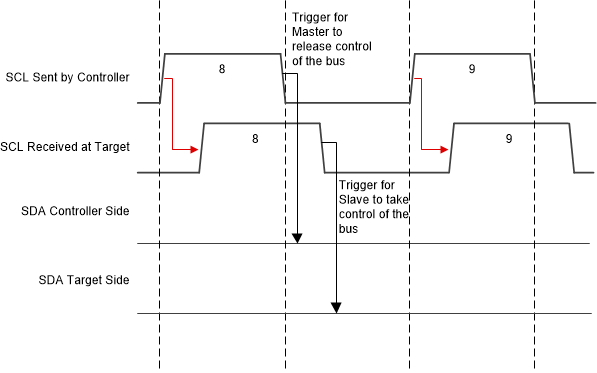
The propagation delay does impact the timing for the target device to take control of the bus during the ACK portion of the signaling with respect to the controller. Figure 3-2 shows a zoomed-in illustration of what occurs after the falling edge of the eighth clock pulse. After the falling edge of the eighth clock pulse, the open-drain driver of the controller needs to tri-state to give up control of the SDA line so that the target can take control of the SDA signal to ACK to the controller. However, there is a delay before the target receives the message to take control of the bus.
 Figure 3-2 Eighth to Ninth Clock Cycle Zoomed
in With Propagation Delay From Buffer
Figure 3-2 Eighth to Ninth Clock Cycle Zoomed
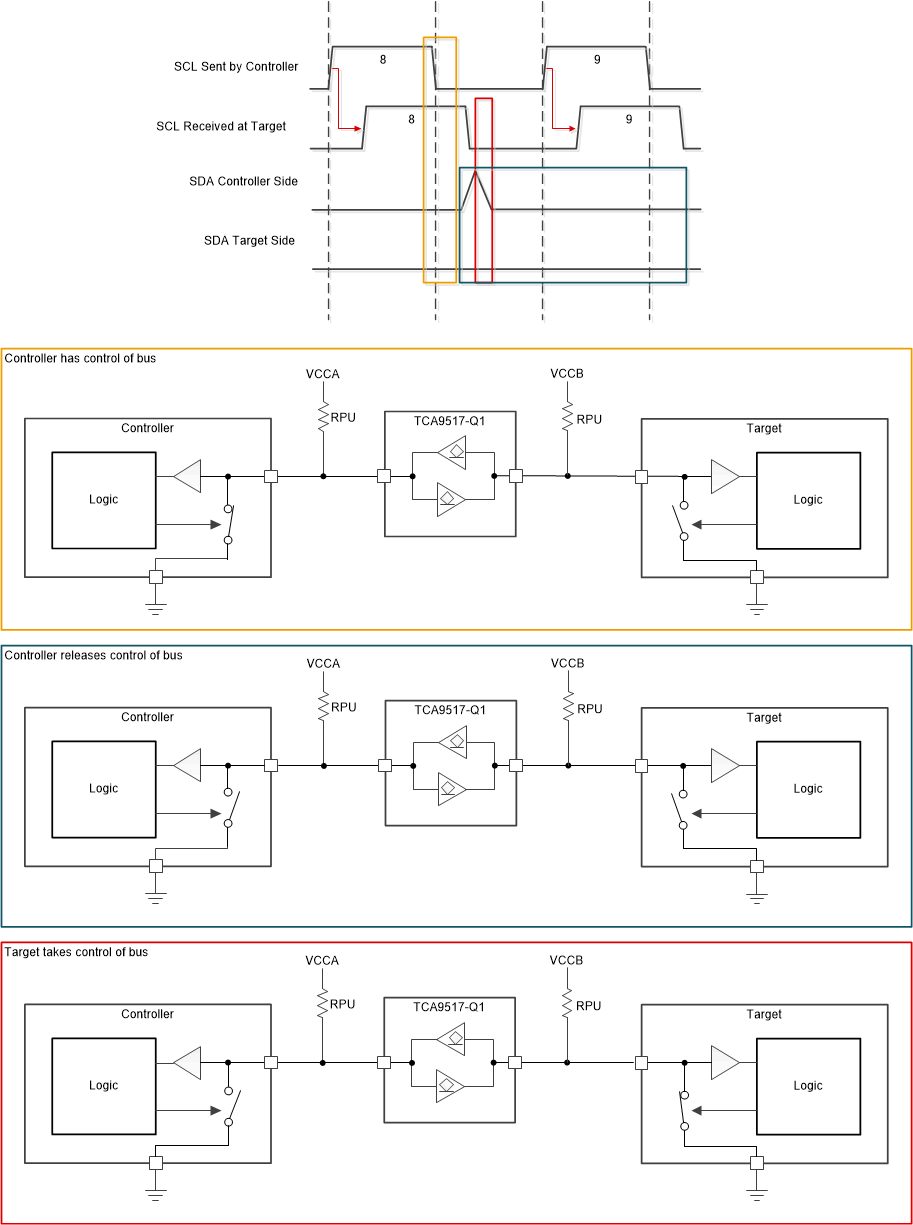
in With Propagation Delay From BufferThis delay in the SCL line being received by the target may result in a small window where the controller has released control of SDA, but the target has not yet taken control of the SDA signal yet because it has not seen the SCL signal go low. Figure 3-3 shows how this circumstance occurs in the system.
 Figure 3-3 SDA Handoff Delay
Illustration
Figure 3-3 SDA Handoff Delay
IllustrationDuring the window where the controller has released control of the bus and the target has not taken control of the bus, the SDA line on the side of the controller begins to rise. This occurs on the A side of the TCA9517, since there are no other external open-drain drivers driving the SDA line low. Before the rising SDA signal is able to traverse through the TCA9517 from the A side to the B side, the SCL signal has already reached the target device to signal for the target to take control of the bus. At this point, the target is able to take control of SDA before the SDA line starts to rise on the target side (the B side of the TCA9517 in this example).