SLAAE71 December 2022 MSPM0G1105 , MSPM0G1106 , MSPM0G1107 , MSPM0G1505 , MSPM0G1506 , MSPM0G1507 , MSPM0G3105 , MSPM0G3106 , MSPM0G3107 , MSPM0G3505 , MSPM0G3506 , MSPM0G3507
- Abstract
- Trademarks
- 1Overview
- 2Low-Power Features in PMCU
- 3Low-Power Optimization
- 4Power Consumption Measurement and Evaluation
2.1.2 Power Management (PMU)
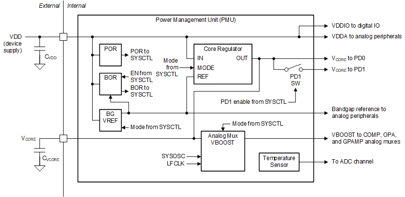
The power management unit (PMU) generates the regulated core supplies for the device and provides supervision of the external supply. It also contains a bandgap voltage reference used by the PMU and other analog peripherals.
See from Figure 2-2, the power management unit (PMU) can provides supervision of the external supply, which is a common function in low-power application. Besides, PD0, PD1 and analog peripherals can be dedicated controlled to realize different power levels.
 Figure 2-2 MSPM0Gxx PMU Block Diagram
There are two supply supervisor circuits available. First is the fixed power-on reset (POR) circuit to indicate that the external supply has reached sufficient for the device to run correctly. Second is the user-programmable brownout reset (BOR) circuit which ensures that the external supply is maintained at a sufficient voltage to support correct operation of the device, which can be configured to other three BOR levels after startup.