SLAAEB3 may 2023 MSPM0L1106 , MSPM0L1106
PRODUCTION DATA
4.1 Read Alarm Status
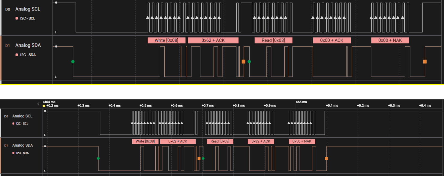
Table 4-1 shows how to read the alarm status of BQ76952. The BQ769x2 ReadAlarmStatus function can be used to retrieve the alarm bits. As Figure 4-1 shows, the read back value is zero before configuring the BQ76952, and related bits change after BQ769x2_Init. The data is returned in little byte order format, in the following example, the 16-bit Alarm Status read 0x5082, which corresponds to a bit is set in Safety Status A (), full voltage scan complete, and voltage ADC scan complete. More description of register can be found in the technical reference manual.
| Command | Name | Unit | Type | Description |
|---|---|---|---|---|
| 0x62 | Alarm Status | Hex | H2 |
Latched signal used to assert the ALERT pin. Write a bit high to clear the latch. Bit descriptions can be found in Alarm Status Register. |
 Figure 4-1 Captured I2C Waveform for
Alarm Status Reading