SLLA607 may 2023 MAX3222E , MAX3227E , MAX3243-EP , MAX3243E , SN75155 , TRS202E , TRS3122E , TRS3221E , TRS3223-Q1 , TRS3243E
3.2 Switching and Timing Characteristics
This section defines the switching characteristics and timing characteristics of common drivers and receivers.
- Common Driver Switching Characteristics and Timing Characteristics (DR, tPHL, tPLH, tsk(p) , and SR(tr))
- DR refers to the maximum data rate of the transceiver. RS-232 only requires 20Kbps, however many devices can go up to 1Mbps. This value is specified with a resistor and capacitor representing 50 feet of cabling + a resistor to model the input impedance of the RS-232 device RX bus pin. For best performance limit the maximum speed of application to the minimum data rate listed in the device data sheet.
- tPHL and tPLH are the propagation delay times from high to low and low to high, respectively. This value measures the time from an input signal reaching 50% of its value to the output reaching 50% of its value. tPHL is a negative output voltage swing while tPLH is a positive output voltage swing

Figure 3-1 Example TPHL and TPLH Test Setup from the TRSF3243E Data Sheet - tsk(p) is the pulse skew of the driver. Figure 3-1 looks at the magnitude of difference between tPHL and tPLH - since in real devices these times typically only vary slightly. The higher the skew is in the system, the more additive jitter exists in the system because skew changes the periodicity of the data signal.
- SR(tr) is the slew rate during the transition region of the driver output. SR(tr) measures the voltage output per microsecond of the device in the linear region of operation (typically 10% to 90% of signal value). SR(tr) gives an idea of how fast the transition speed is and can help determine what frequency content is generated during switching. The change in voltage magnitude divided by the duration of the change is the slew rate.

Figure 3-2 Slew Rate Test Setup Example from TRSF3243E Data Sheet
- Common Receiver Switching Characteristics and Timing Characteristics (TPHL, TPLH, Tsk(p), Ten, and Tdis)
- tPHL, tPLH, and tsk(p) are all the same characteristics as described in the previous section on driver timing and switching characteristics. The only difference is that these parameters are measured from the input on RX bus pins to the output on RX console output pins.
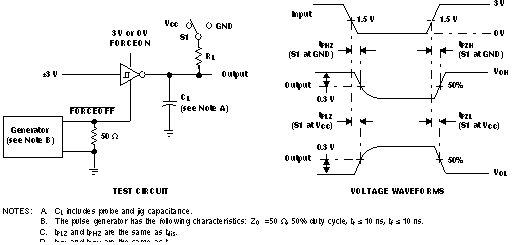
- ten and tdis refer to the enable time and disable time of the device. These specifications determine how long it takes the device to become active from a shutdown state or how long to put the device into a shutdown state, respectively.

Figure 3-3 Enable and Disable Time Test Setup Example from the TRSF3243E Data Sheet