SLUA963B June 2020 – October 2022 UCC21710-Q1 , UCC21732-Q1 , UCC5870-Q1
- HEV/EV Traction Inverter Design Guide Using Isolated IGBT and SiC Gate Drivers
- 1Introduction
- 2HEV/EV Overview
-
3Design of HEV/EV Traction Inverter Drive Stage
- 3.1 Introduction to UCC217xx-Q1
- 3.2 Designing a Traction Inverter Drive System Using UCC217xx-Q1
- 3.3 Description of Protection Features
- 3.4 Protection Features of UCC217xx-Q1
- 3.5
UCC217xx-Q1 Protection and Monitoring Features Descriptions
- 3.5.1 Primary and Secondary Side UVLO and OVLO
- 3.5.2 Over-Current (OC) and Desaturation (DESAT) Detection
- 3.5.3 2-Level and Soft Turn-Off
- 3.5.4 Power Switch Gate Voltage (VGE/VGS) Monitoring
- 3.5.5 Power Switch Anti-Shoot-Through
- 3.5.6 Integrated Internal or External Miller Clamp
- 3.5.7 Isolated Analog-to-PWM Channel
- 3.5.8 Short-Circuit Clamping
- 3.5.9 Active Pulldown
- 3.6 Introduction to UCC5870-Q1
- 3.7 Designing a Traction Inverter Drive System Using UCC5870-Q1
- 3.8 Description of Protection Features
- 3.9 Protection Features of UCC5870-Q1
- 3.10
UCC5870-Q1 Protection and Monitoring Features Descriptions
- 3.10.1 Primary and Secondary Side UVLO and OVLO
- 3.10.2 Programmable Desaturation (DESAT) Detection and Over-Current (OC)
- 3.10.3 Adjustable 2-Level or Soft Turn-Off
- 3.10.4 Active High-Voltage Clamp
- 3.10.5 Power Switch Gate Voltage (VGE/VGS) Monitoring
- 3.10.6 Gate Threshold Voltage Monitor
- 3.10.7 Power Switch Anti-Shoot-Through
- 3.10.8 Active Short Circuit (ASC)
- 3.10.9 Integrated Internal or External Miller Clamp
- 3.10.10 Isolated Analog-to-Digital Converter
- 3.10.11 Short-Circuit Clamping
- 3.10.12 Active and Passive Pulldown
- 3.10.13 Thermal Shutdown and Temperature Warning of Driver IC
- 3.10.14 Clock Monitor and CRC
- 3.10.15 SPI and Register Data Protection
- 4Isolated Bias Supply Architecture
- 5Summary
- 6References
- 7Revision History
3.5.3 2-Level and Soft Turn-Off
As mentioned in the previous section, short circuit detection sends back a fault indication and triggers the driver to turn off the IGBT or SiC MOSFET. The driver initiates either 2-level turn-off or soft turn-off to safely shut down the IGBT or MOSFET, preventing large voltage overshoot across the device as a result of the high current transient.
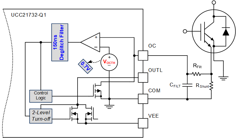
2-level turn-off, shown in Figure 3-7, slows down the turn-off transient by pulling the gate to a mid-level voltage, 9 V, during the turn-off transition to reduce the channel current flow through the device. This significantly reduces the energy dissipation during the fault event. After the second voltage level is applied for a period of time, the driver finally pulls the gate down to VEE using a soft pull down current to transition smoothly to the off-state.
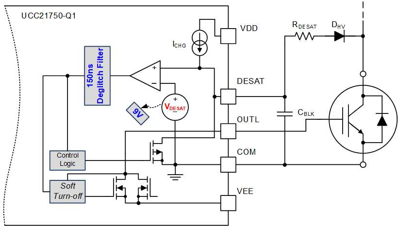
Soft turn-off, shown in Figure 3-8, uses a soft pull down current throughout the entire turn-off transition as opposed to applying a specified gate voltage. The 400 mA current causes the device to transition at a slower rate than it would with a hard turn-off, and thus reduces voltage overshoot while minimizing the amount of energy dissipation.
The inverter benefits not only to prevent the damage or destruction of the power switches, but also prevents high-voltages from being applied to the motor windings, which can also reduce the lifetime of the motor itself.
 Figure 3-7 2-Level Turn-Off Block (UCC21732-Q1)
 Figure 3-8 Soft Turn-Off Block (UCC21750-Q1, UCC21710-Q1)