SLVAF43 May 2021 TPS65235 , TPS65235-1 , TPS652353
2 Solutions
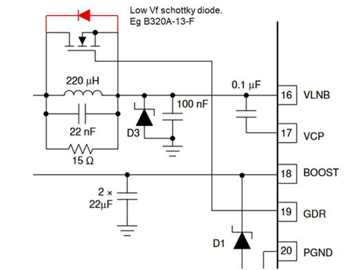
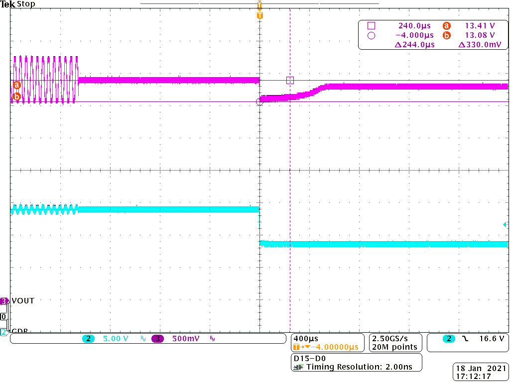
To avoid this negative spike, a couple of options are available. One is to add a Schottky diode across the FET as shown in Figure 2-1. This diode clamps the spike similar to the FET body diode, but with a lower forward voltage. Figure 2-2 shows the output with a B320A-13-F Schottky diode added. The spike is still present but is reduced to approximately 330 mV.
 Figure 2-1 Schottky Diode Added to Clamp
Negative Spike
 Figure 2-2 Spike Clamped to Approximately 330 mV by Adding Schottky Diode Across
the FET
Figure 2-2 Spike Clamped to Approximately 330 mV by Adding Schottky Diode Across
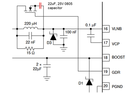
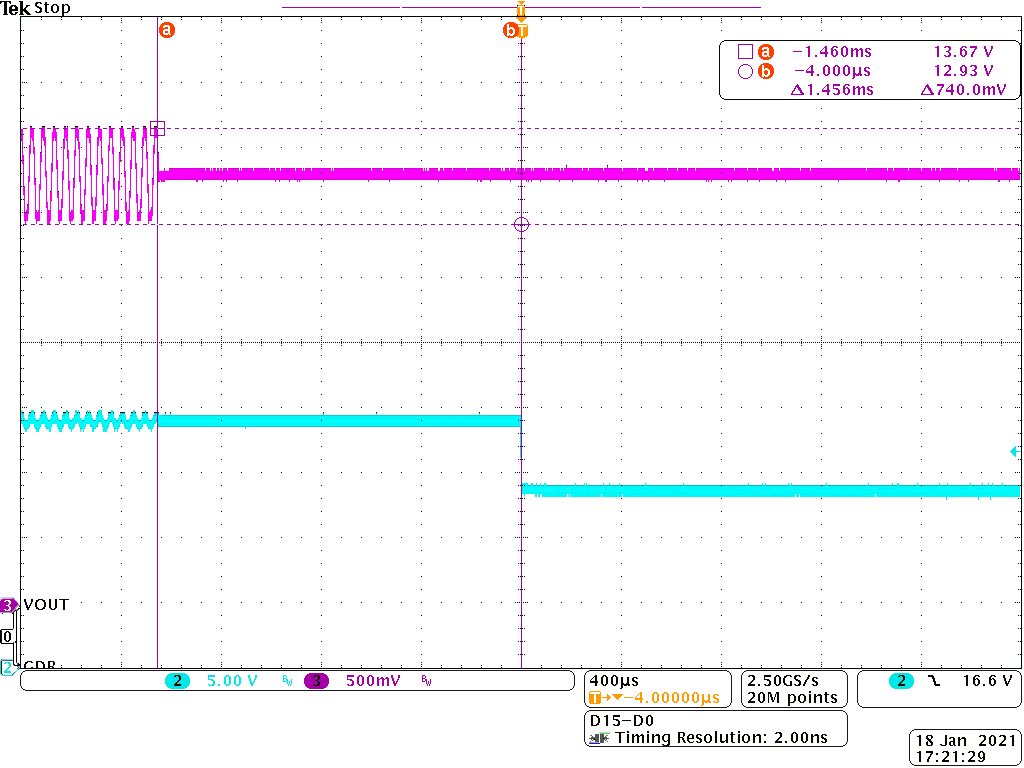
the FETAnother solution is to add a DC blocking capacitor in series with the FET as shown in Figure 2-3. In this way, when the FET is turned on, the 22-kHz tone passes through the capacitor whose impedance is approximately 330 mΩ at 22 kHz. However, the DC current is blocked and continues to flow via the inductor. So when the FET is turned off there is no change in the DC current flow and no negative spike is generated (Figure 2-4). A 22-µF, 25-V with 0805 capacitor was used for this test, but similar results were achieved with a 10-µF, 25-V capacitor. In normal working conditions, the voltage across the capacitor is less than 2 V but, as the output may be subjected to surges, a 25-V rated capacitor is recommended.
 Figure 2-3 DC Blocking Capacitor Added in Series With FET
 Figure 2-4 Inserting a 22-µF Blocking
Capacitor Removes the Negative Spike Entirely