SLVAF59 April 2021 TPS2372 , TPS2373 , TPS23730 , TPS23731 , TPS23734 , TPS2375 , TPS2375-1 , TPS23750 , TPS23751 , TPS23752 , TPS23753A , TPS23754 , TPS23754-1 , TPS23755 , TPS23756 , TPS23757 , TPS23758 , TPS2376 , TPS2376-H , TPS2377 , TPS2377-1 , TPS23770 , TPS2378 , TPS2379
3.1 DCDC IC Settings
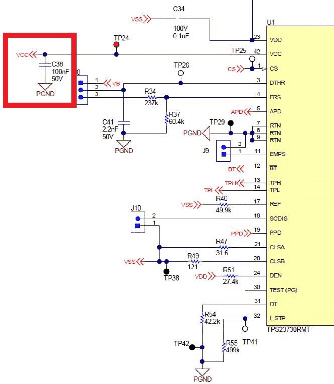
These settings are resistors on the IC that set characteristics of the DCDC. VCC: needs a bypass capacitor – 0.1uF:
 Figure 3-1 VCC Bypass Capacitor
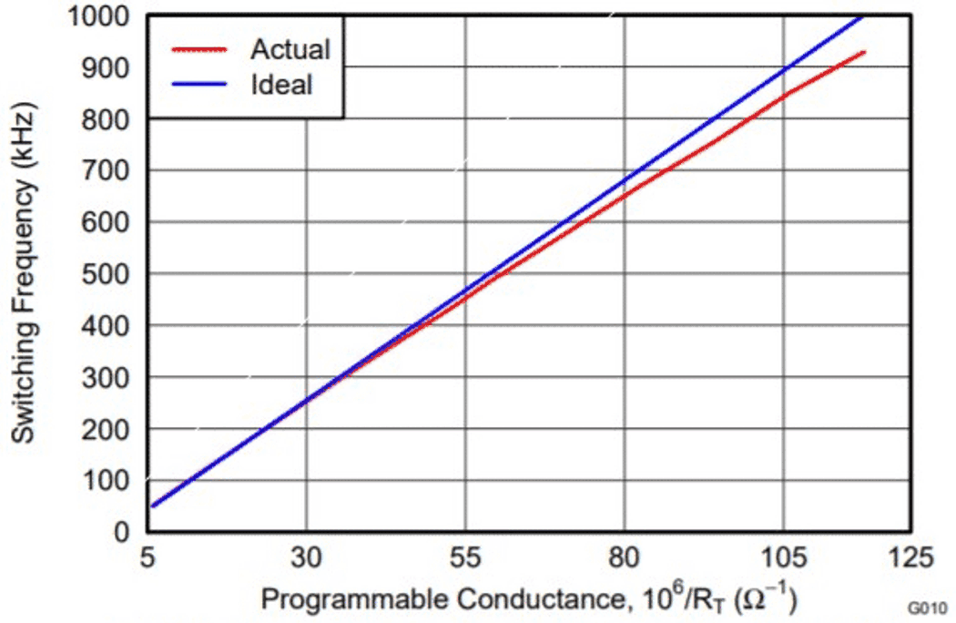
FRS sets the switching frequency. This is typically set to 250kHz since that has been found to be the optimal switching frequency to maximize efficiency for the typical PoE input range and output voltage. Other ranges can be set but ensure the transformer is rated for the appropriate switching frequency. Each IC as a chart that shows the resistor chosen vs the switching frequency.
 Figure 3-2 FRS Resistor Setting Chart
Example
Figure 3-2 FRS Resistor Setting Chart
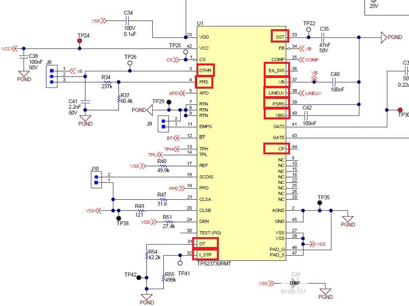
Example- DTHR sets dithering. Ensure that it is either enabled (connected to FRS somehow) or disabled (connected to VB). Not both
- DT sets the deadtime (if there are two gate drives). For 250kHz switching frequency this should be between 40ns and 90ns (typically ). Please note that topologies that do not require a second gate drive but the part has one, DT must be connected to VB in order to work.
- I_STP sets the soft-stop rate (by setting the current that drains out of the SST cap). Typically, 499K is fine.
- SST needs a capacitor to set the soft-start and soft-start times
- Vb needs a bypass capacitor – usually 0.1uF
- Vbg needs a capacitor
- PSRS sets the primary side regulation topology – diode or synchronous --- if used at all
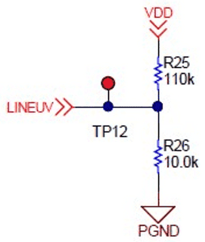
- LineUV sets the IC shutdown voltage level – the IC monitors the input voltage through LINEUV. So, set the shutdown level to usually 37V. This will set the voltage that soft-stop turns on. A divider is usually the same for all designs since the input voltage and shutdown voltage do not change
 Figure 3-3 LINEUV Resistor
Divider
Figure 3-3 LINEUV Resistor
DividerIf PSR is used CP will need a resistor and cap to clamp the internal FET for sync flybacks.
 Figure 3-4 DCDC Pin Settings