SLVAFL3 april 2023 BQ25890H
- Abstract
- Trademarks
- 1Introduction
-
2DPDM Structure of BQ25890H
- 2.1 DPDM Block Diagram and Working Flow Chart
- 2.2 Key Register Configuration for BC1.2/HVDCP Standard Power Source with DPDT Signal Switch
- 2.3 Key Register Configuration for BC1.2/HVDCP Standard Power Source Without DPDT Signal Switch
- 2.4 Fast Charging Configuration for PPS/HVDCP Power Source with BQ25890H
- 3References
2.4.1 Working Mechanism with PPS/HVDCP Source
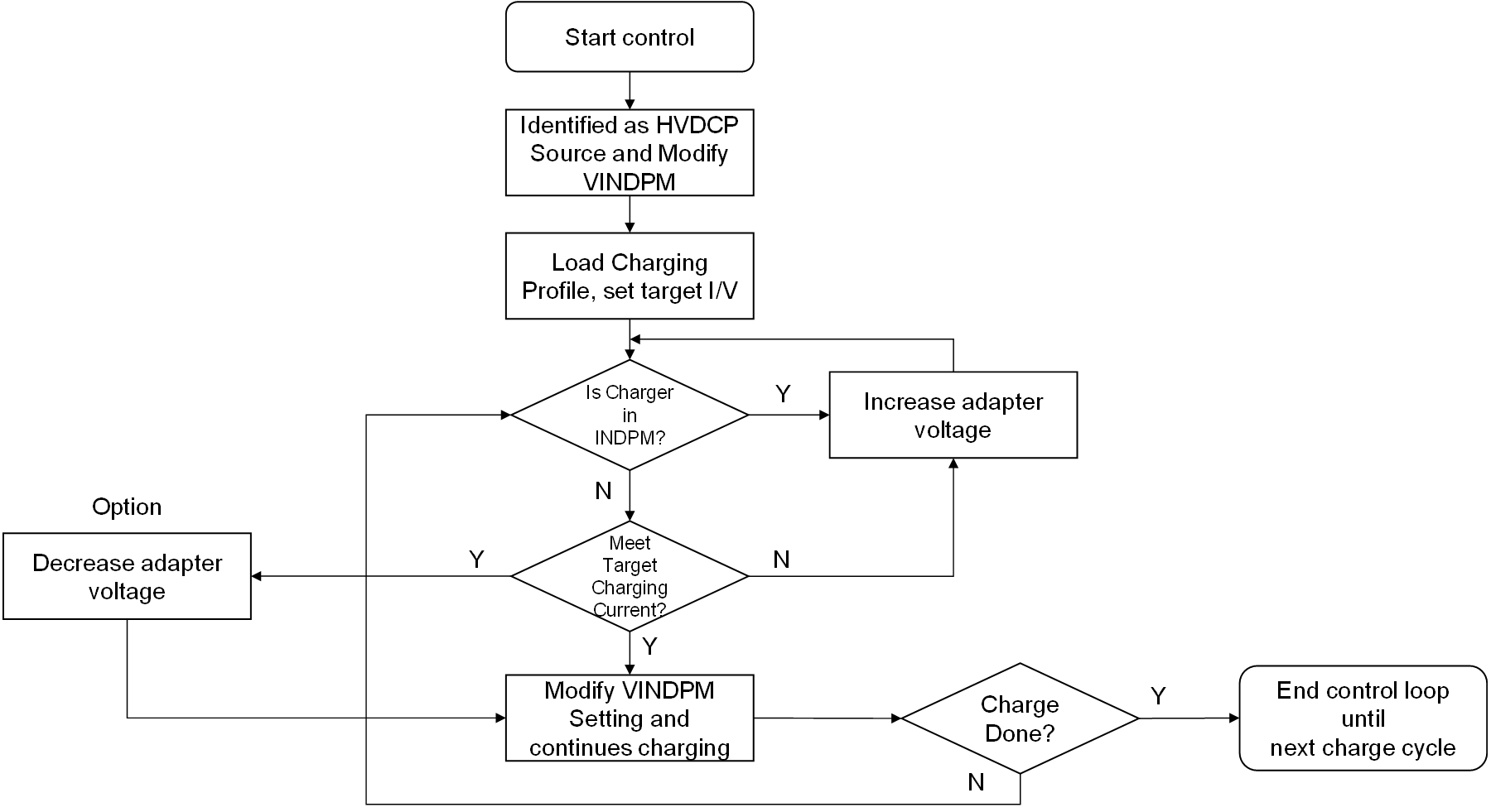
In general, for higher efficiency and power in fast charging mode, PPS/HVDCP power source would be better candidate compare to fixed 5-V adapter. BQ25890H can support this kind of application by using programmable DPDM interface. Design engineer can monitor the status of IINDPM/VINDPM in BQ25890H to adjust PPS/HVDCP output voltage so as to meet target charging power, such as 18 W or more. IINDPM means, when the output power of PPS/HVDCP adapter cannot reach target charging power, BQ25890H will indicate IINDPM signal to AP, AP will send control command to PPS/HVDCP adapter by DPDM port to ask more power from PPS/HVDCP adapter, or increase the output voltage of PPS/HVDCP adapter until target charging power is satisfied. Meanwhile, higher output voltage of AC adapter can decrease power dissipation on the cable of AC adapter further. Another option is that if IINDPM is not triggered but target charging current is reached, it means the output voltage of adapter would be a little higher than expected, so AP will send command to adapter to decrease voltage of adapter to get higher efficiency (lower differential voltage between input and output in buck charger will get higher efficiency).
 Figure 2-6 HVDCP/PPS Fast Charging Flow
Chart