SLVUCO1A May   2023  – April 2024 DRV8213 , DRV8214 , DRV8234

PRODUCTION DATA  

  1.   1
  2.   Description
  3.   Get Started
  4.   Features
  5.   Applications
  6.   6
  7. 1Evaluation Module Overview
    1. 1.1 Introduction
    2. 1.2 Kit Contents
    3. 1.3 Specification
    4. 1.4 Device Information
  8. 2Hardware
    1. 2.1 Headers and Test Points Information
    2. 2.2 Connector Information
    3. 2.3 Indicator LEDs
    4. 2.4 Hardware Setup
  9. 3Software
    1. 3.1 Software Setup
    2. 3.2 Web GUI Access or Local GUI Installation
    3. 3.3 Connecting EVM to GUI
    4. 3.4 GUI Overview
    5. 3.5 DRV8213EVM
    6. 3.6 DRV8214EVM, DRV8215EVM, DRV8234EVM, and DRV8235EVM
      1. 3.6.1 Quick Start
      2. 3.6.2 Dashboard
      3. 3.6.3 Register Map
    7. 3.7 Scripting Window
  10. 4Hardware Design Files
    1. 4.1 Schematics
    2. 4.2 PCB Layout
    3. 4.3 Bill of Materials (BOM)
  11. 5Additional Information
    1. 5.1 Trademarks
  12. 6Revision History

DRV8213EVM

Figure 4-6 provides the overview of all the widgets and features of the DRV8213EVM GUI.
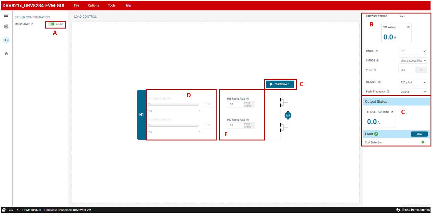
GUID-20230321-SS0I-SWNH-SNTC-KWFJCVXHZMNC-low.png Figure 3-6 DRV8213 GUI Driver Control Page
Table 3-1 DRV8213EVM GUI Overview

Component

Description

A

Device enable. Set slider to GREEN position to enable the driver.

B

  1. Firmware Version: EVM firmware version.
  2. VM voltage: supply voltage value.
  3. IMODE: current regulation mode (OFF: regulation disabled; ON: regulation always enabled; INRUSH: enabled only during inrush).
  4. SMODE: stall mode (LOW: latched nFAULT with outputs disabled; HIGH: nFAULT indication only with outputs remaining enabled; Hi-Z: NFAULT indication only with internal VREF=500mV).
  5. VREF: VREF value (range of 0V-3.3V).
  6. GAINSEL: current sense amplifier gain selection.
  7. PWM frequency: Switching PWM frequency selector. Default value is 25kHz and up to 100kHz.

Col

  1. Bridge Current: Output current (currently not functional. GUI to be updated)
  2. nFAULT: Fault status. Mirrors nFAULT LED (D11).
  3. CLEAR: click to clear fault or stall warning.
  4. STALL DETECTION: turns yellow when stall is detected. Cleared by pressing CLEAR button.
D IN1 and IN2 duty cycle control widget. Duty cycle ranges from 0-100 at the user selected PWM frequency. The duty cycle is adjustable by using the slider or writing to the input box.
E IN1 and IN2 ramp rate. The PWM slowly ramps up or down the duty cycle to avoid sudden speed changes. The ramp rate is adjustable from 0-25 with 0=no ramp and 25=slowest ramp rate.