SLVUCO1A May   2023  – April 2024 DRV8213 , DRV8214 , DRV8234

PRODUCTION DATA  

  1.   1
  2.   Description
  3.   Get Started
  4.   Features
  5.   Applications
  6.   6
  7. 1Evaluation Module Overview
    1. 1.1 Introduction
    2. 1.2 Kit Contents
    3. 1.3 Specification
    4. 1.4 Device Information
  8. 2Hardware
    1. 2.1 Headers and Test Points Information
    2. 2.2 Connector Information
    3. 2.3 Indicator LEDs
    4. 2.4 Hardware Setup
  9. 3Software
    1. 3.1 Software Setup
    2. 3.2 Web GUI Access or Local GUI Installation
    3. 3.3 Connecting EVM to GUI
    4. 3.4 GUI Overview
    5. 3.5 DRV8213EVM
    6. 3.6 DRV8214EVM, DRV8215EVM, DRV8234EVM, and DRV8235EVM
      1. 3.6.1 Quick Start
      2. 3.6.2 Dashboard
      3. 3.6.3 Register Map
    7. 3.7 Scripting Window
  10. 4Hardware Design Files
    1. 4.1 Schematics
    2. 4.2 PCB Layout
    3. 4.3 Bill of Materials (BOM)
  11. 5Additional Information
    1. 5.1 Trademarks
  12. 6Revision History

Indicator LEDs

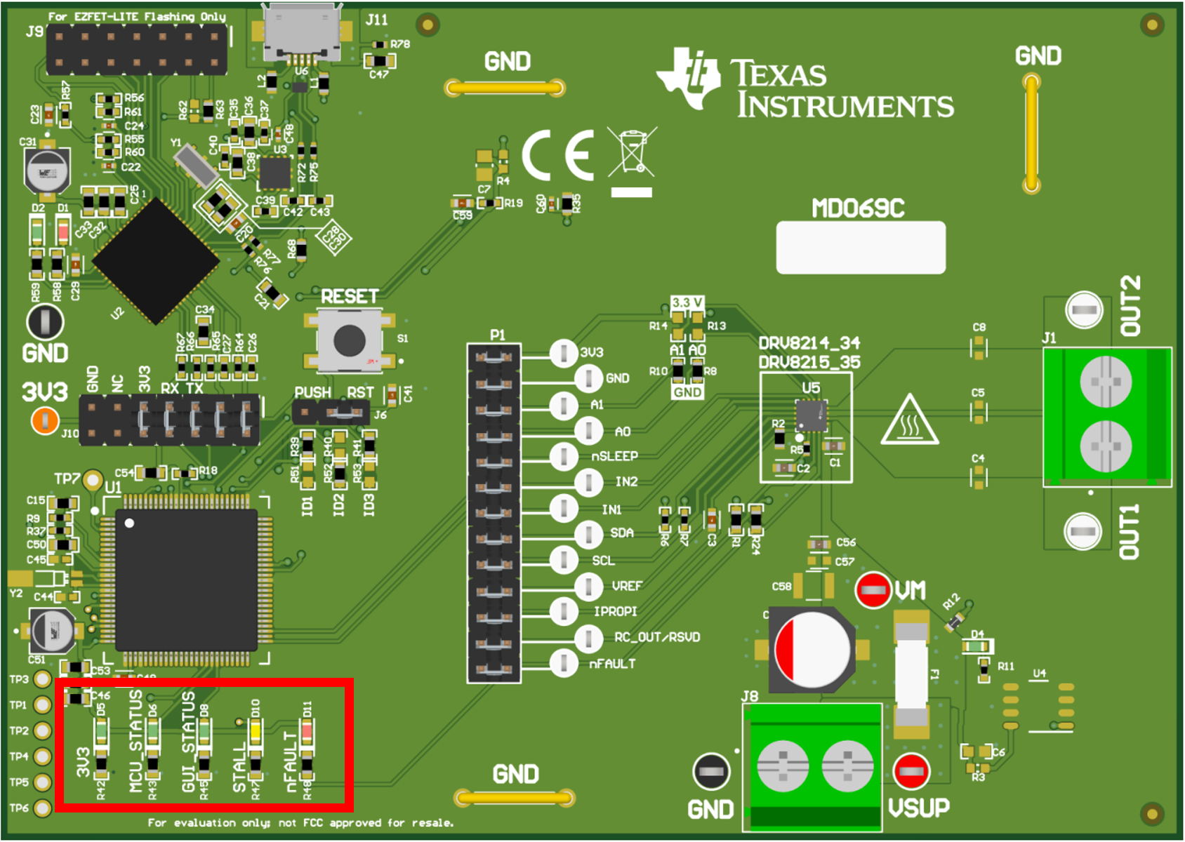
GUID-20240318-SS0I-SHW8-PSK8-PFVW4HRS44Z2-low.png Figure 2-5 LED indicators
LEDFunction
D4VM: ON when VSUP or VM is connected and turned on.
D53V3: OFF when 3.3V is not active. ON when 3.3V is active
D6MCU_STATUS: LED toggles at a rate of around 1s when MCU is active. Unplug and reconnect the EVM to the computer if this stops flashing.
D8GUI_STATUS: LED toggles when EVM is communicating with GUI software. LED OFF means there is no communication with GUI.
D10STALL: OFF when no motor stall is detected by DRV. ON when motor stall is detected.
D11nFAULT: OFF when no fault present. ON when DRV flags a fault.