SLYT841 july 2023 ADS1261
3 Transient currents
One challenge with transient currents is that their magnitude and duration can vary significantly as a result of the ADC operating conditions and surrounding circuitry. ADC data sheets therefore rarely specify transient currents. However, it is possible to measure transient currents for a given system configuration by probing with an oscilloscope across a small-value resistor placed in series with the power-supply trace. You can then use Ohm’s law to determine the resulting current.
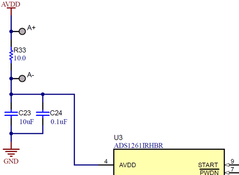
The ADS1261 has an evaluation module (EVM) that incorporates such a resistor between the power-supply output and the ADC AVDD pin. Figure 1 shows the relevant portion of the EVM schematic that includes a 10-Ω measurement resistor (R33). Measuring the average or transient voltage drop across this resistor and then dividing by 10 Ω calculates the average or transient current drawn by the ADS1261, respectively. I performed multiple tests under a variety of conditions to better understand the transient current behavior of this ADC.
 Figure 1 Transient current test circuit
using the ADS1261 EVM.
Figure 1 Transient current test circuit
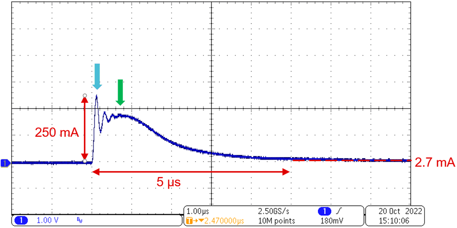
using the ADS1261 EVM.The first transient current test was a power-up test with the recommended 10-µF (C23) and 0.1-µF (C24) decoupling capacitors from AVDD to ground installed. Figure 2 shows the ADS1261 transient current under these conditions.
 Figure 2 Measured transient current at
power up with decoupling capacitors installed.
Figure 2 Measured transient current at
power up with decoupling capacitors installed.Recall from the ADS1261 power-supply specifications in Table 1 that the average current with the PGA disabled is 2.7 mA (typical) or 4.5 mA (maximum). However, the blue arrow in Figure 2 points to a 250-mA transient spike that occurs when the ADS1261 is initially powered. This transient is >90 times the typical current and >55 times the maximum current specified in the data sheet. Similar current spikes can occur when the ADC undergoes any change in state.
The green arrow in Figure 2 identifies a second transient current required to charge up the decoupling capacitors. Under normal operating conditions, the decoupling capacitors store supplemental charge to provide extra current when transients occur. This extra charge helps maintain a steady supply voltage such that ADC operation remains unaffected. The capacitors must be charged up to the supply voltage from an uncharged state when the system is powered, however. Unpowered capacitors behave like a short at the instant the system powers up, resulting in a large inrush current. The magnitude of the inrush current increases as the value of the decoupling capacitor increases.
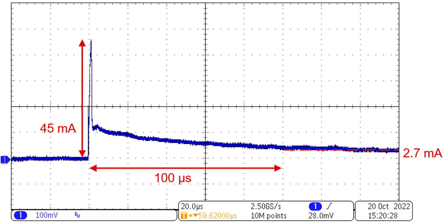
To measure only the transient current that the ADC requires, the second transient current test removed the recommended 10- and 0.1-µF decoupling capacitors from AVDD to ground in Figure 1. Figure 3 shows the ADS1261 transient current under these conditions.
 Figure 3 Measured transient current at
power up with decoupling capacitors removed.
Figure 3 Measured transient current at
power up with decoupling capacitors removed.The 45-mA transient spike in Figure 1 represents only the power-up current required by the ADC attributable to switching. As expected, the ADC-only transient is smaller compared to the 250-mA spike that occurred when the decoupling capacitors were installed. However, this reduced transient magnitude comes at the cost of a significantly longer time for the ADC to reach the steady-state current because the capacitors no longer provide any supplemental charge. Additionally, this 45-mA transient is still 10 times the maximum ADC current specification of 4.5 mA listed in Table 1.
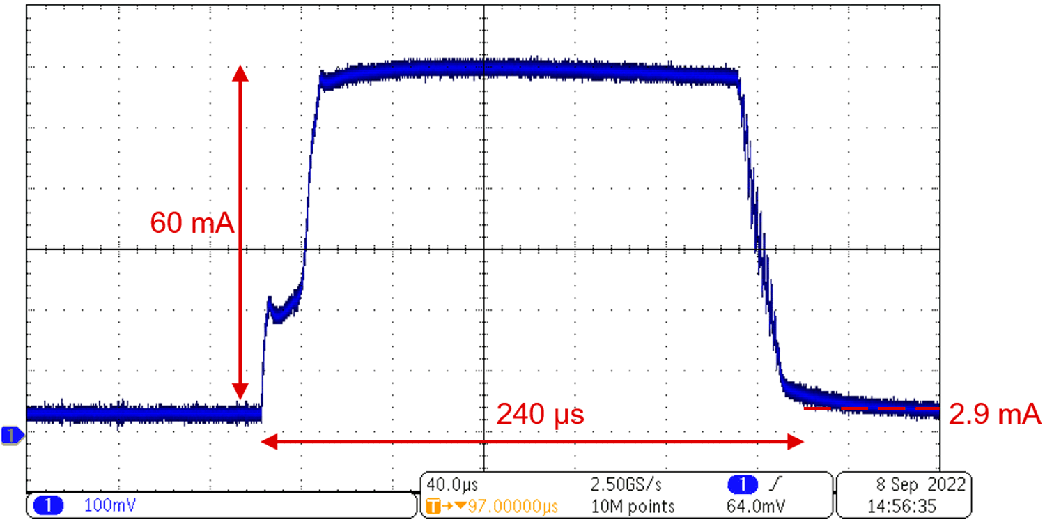
I performed a third set of tests to verify that different functions can also cause transient current spikes. Enabling the ADS1261 VREF was one such function that produced a spike. Figure 4 shows the observed behavior of this transient current.
 Figure 4 Measured transient current
with the ADS1261 VREF enabled.
Figure 4 Measured transient current
with the ADS1261 VREF enabled.Recall from Table 1 that the typical ADS1261 VREF current is 0.2 mA. Operating the ADC with the PGA disabled (2.7 mA) and the internal VREF enabled should yield 2.9 mA of total current. However, the 60-mA measured transient current in Figure 4 is >20 times the expected value. This transient largely results from the inrush current required to charge a filtering capacitor placed between the VREF output pin and ground.
One interesting characteristic of Figure 4 is that the current demand remains constant at 60 mA for essentially the entire transient pulse. This behavior results from an inherent current limit designed into the ADS1261 internal VREF, which helps protect the ADC in case the REFOUT pin shorts to ground.
I performed some additional function tests that did not show any measurable transient current, although I did not test all operating conditions. Also, I should note that this behavior is not limited to the ADS1261; it is possible to observe the transient currents documented in this article with all precision ADCs.