SLYY197A october 2020 – october 2020 BQ79600-Q1 , BQ79606A-Q1 , BQ79616-Q1 , CC2642R-Q1
Wired vs. wireless BMS considerations
The focus in this paper will be on the communications interface between each battery monitor device connected in the pack and the host MCU. Both examples will use the BQ796xx family of monitors. The typical wired solution connects battery monitors in a daisy-chain cable with twisted-pair cabling between battery modules. The wireless communication method uses the CC2642R-Q1 wireless MCU for transmitting data.
In Figure 2, the wired solution displays a battery management or monitor unit (BMU) board on the left, which holds the host MCU and BQ79600-Q1 communications bridge device. This BMU acts as an interface between the MCU and other BQ796xx monitoring devices on the cell monitoring unit (CMU), which connects to the actual battery cells. These CMUs are interconnected through a twisted-pair daisy-chain cable on both the high and low sides of each battery monitor device, and there is an optional ring cable that provides the ability to transmit in either direction in the event of a cable break. The wired solution does require isolation components on either side of the daisy-chain cabling to ensure robust communication in noisy environments that can withstand strict automotive electromagnetic interference (EMI) and electromagnetic compatibility (EMC) limits.
The wireless solution uses a wireless interface to transmit universal asynchronous receiver-transmitter (UART) data from the battery monitor to the host MCU via a wireless transceiver device.
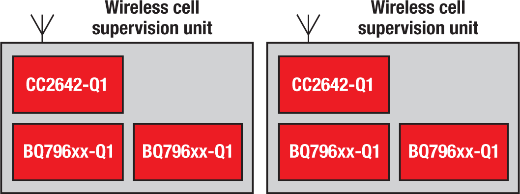
Figure 3 uses a more simplified representation of a CMU than Figure 1, but adds a wireless receiver node to show that the CMU has an additional device to transmit cell data wirelessly back to the host. This enables the two CMUs shown in Figure 2 to be naturally isolated from one another.
 Figure 3 Wireless BMS Example.
The significant difference between both solutions comes down to the replacement of the twisted-pair cabling in the wired solution with a CC2642R-Q1 device on each BMU in the wireless solution.
It may appear that adding an extra device may create more complexity and cost more than cabling, but consider the cost and weight of the cabling and the need to place high-performance isolation components on either side of the twisted-pair interface to ensure communication robustness. Table 1 outlines further considerations for wired vs. wireless battery manangement solutions.