SPRACN0F October 2021 – March 2023 TMS320F280021 , TMS320F280021-Q1 , TMS320F280023 , TMS320F280023-Q1 , TMS320F280023C , TMS320F280025 , TMS320F280025-Q1 , TMS320F280025C , TMS320F280025C-Q1 , TMS320F280033 , TMS320F280034 , TMS320F280034-Q1 , TMS320F280036-Q1 , TMS320F280036C-Q1 , TMS320F280037 , TMS320F280037-Q1 , TMS320F280037C , TMS320F280037C-Q1 , TMS320F280038-Q1 , TMS320F280038C-Q1 , TMS320F280039 , TMS320F280039-Q1 , TMS320F280039C , TMS320F280039C-Q1 , TMS320F280040-Q1 , TMS320F280040C-Q1 , TMS320F280041 , TMS320F280041-Q1 , TMS320F280041C , TMS320F280041C-Q1 , TMS320F280045 , TMS320F280048-Q1 , TMS320F280048C-Q1 , TMS320F280049 , TMS320F280049-Q1 , TMS320F280049C , TMS320F280049C-Q1 , TMS320F28374D , TMS320F28374S , TMS320F28375D , TMS320F28375S , TMS320F28375S-Q1 , TMS320F28376D , TMS320F28376S , TMS320F28377S , TMS320F28377S-Q1 , TMS320F28378D , TMS320F28378S , TMS320F28379D , TMS320F28379D-Q1 , TMS320F28379S , TMS320F28384D , TMS320F28384S , TMS320F28386D , TMS320F28386S , TMS320F28388D , TMS320F28388S , TMS320F28P650DH , TMS320F28P650DK , TMS320F28P650SH , TMS320F28P650SK , TMS320F28P659DH-Q1 , TMS320F28P659DK-Q1 , TMS320F28P659SH-Q1
- The Essential Guide for Developing With C2000™ Real-Time Microcontrollers
- Trademarks
- 1C2000 and Real-Time Control
-
2Sensing Key Technologies
- 2.1 Accurate Digital Domain Representation of Analog Signals
- 2.2 Optimizing Acquisition Time vs Circuit Complexity for Analog Inputs
- 2.3 Hardware Based Monitoring of Dual-Thresholds Using a Single Pin Reference
- 2.4 Resolving Tolerance and Aging Effects During ADC Sampling
- 2.5 Realizing Rotary Sensing Solutions Using C2000 Configurable Logic Block
- 2.6 Smart Sensing Across An Isolation Boundary
- 2.7 Enabling Intra-Period Updates in High Bandwidth Control Topologies
- 2.8 Accurate Monitoring of Real-Time Control System Events Without the Need for Signal Conditioning
-
3Processing Key Technologies
- 3.1 Accelerated Trigonometric Math Functions
- 3.2 Fast Onboard Integer Division
- 3.3 Hardware Support for Double-Precision Floating-Point Operations
- 3.4 Increasing Control Loop Bandwidth With An Independent Processing Unit
- 3.5 Flexible System Interconnect: C2000 X-Bar
- 3.6 Improving Control Performance With Nonlinear PID Control
- 3.7 Understanding Flash Memory Performance In Real-Time Control Applications
- 3.8 Deterministic Program Execution With the C28x DSP Core
- 3.9 Efficient Live Firmware Updates (LFU) and Firmware Over-The-Air (FOTA) updates
-
4Control Key Technologies
- 4.1 Reducing Limit Cycling in Control Systems With C2000 HRPWMs
- 4.2 Shoot Through Prevention for Current Control Topologies With Configurable Deadband
- 4.3 On-Chip Hardware Customization Using the C2000 Configurable Logic Block
- 4.4 Fast Detection of Over and Under Currents and Voltages
- 4.5 Improving System Power Density With High Resolution Phase Control
- 4.6 Safe and Optimized PWM Updates in High-Frequency, Multi-Phase and Variable Frequency Topologies
- 4.7 Solving Event Synchronization Across Multiple Controllers in Decentralized Control Systems
- 5Interface Key Technologies
- 6Safety Key Technologies
- 7References
- 8Revision History
2.1.2 In Depth
The first step when selecting an MCU for a real-time control system is relatively straightforward process; comparing the components of the MCU to the system needs. There are questions of memory size, CPU speed, communications standards used, analog content, number of I/Os, and so forth. When looking at the fit for an analog module like the ADC, it can appear straightforward to base the decision on sampling rate, number of inputs, and bit level. In practice, however, there is much more to this decision.
Too often ADC selection is based solely on the top level specifications, only to realize during development there are limitations to the system performance due to the ADC itself:
- Will the system be using the analog inputs for frequency analysis? Then, AC specifications like SNR and THD become important to consider when picking an MCU with an on-chip ADC.
- Is overall accuracy a key care about? Looking at the DC specifications like INL, Gain, and Offset are key parameters to consider.
A quick summary of ADC specifications and their relevance to the system:- AC Specifications: Parameters related to how accurately the converter can resolve the fundamental frequency tone of a signal from other noise sources. Includes SNR, SINAD, THD, and SFDR all expressed in dB. Also includes ENOB, which is the SINAD translated into number of bits. Typically SINAD and ENOB based on SINAD are considered when choosing an ADC, the importance will vary depending on the end application.
- DC Specifications: Parameters related to the accuracy of the converter as it applies to representing an analog input in the digital domain. Includes Gain, Offset, DNL, and INL. The weighted summation of the Gain, Offset, and INL are often referred to as "Total Unadjusted Error" (Equation 1). This equation is typically used to determine the real-world impact of these parameters on the accuracy of a conversion.
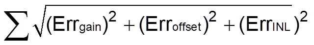
where
- Errgain is the maximum gain error of the ADC in LSBs
- Erroffset is the maximum offset error ADC in LSBs
- ErrINL is the maximum INL error of the ADC in LSBs
An example of how the C2000 ADC is specified and the parameters can be seen in #GUID-C3961371-634F-4011-97EE-A61164A2FE54/T5843526-39, a dynamic link to this same table in the data sheet is located here.
One final aspect of all the parameters that C2000 devices list in the data sheet is what is implied by the inclusion of the parameter itself. For parameters that have a MIN/MAX, these are assured specs over the full operational range and lifetime of the device. The typical (TYP) column is also significant for all parameters, as it represents the mean performance of a parameter across its operational range.
| Parameter | Test Conditions | Min | Typ | Max | Unit |
|---|---|---|---|---|---|
| ADC conversion cycles | 29.6 | 31 | ADCCLKs | ||
| Power-up time (after setting ADCPWDNZ to first conversion) | 500 | µs | |||
| Gain error | –64 | ±9 | 64 | LSBs | |
| Offset error | –16 | ±9 | 16 | LSBs | |
| Channel-to-channel gain error | ±6 | LSBs | |||
| Channel-to-channel offset error | ±3 | LSBs | |||
| ADC-to-ADC gain error | Identical VREFHI and VREFLO for all ADCs | ±6 | LSBs | ||
| ADC-to-ADC offset error | Identical VREFHI and VREFLO for all ADCs | ±3 | LSBs | ||
| DNL | > –1 | ±0.5 | 1 | LSBs | |
| INL | –3 | ±1.5 | 3 | LSBs | |
| SNR | VREFHI = 2.5 V, fin = 10 kHz | 87.6 | dB | ||
| THD | VREFHI = 2.5 V, fin = 10 kHz | –93.5 | dB | ||
| SFDR | VREFHI = 2.5 V, fin = 10 kHz | 95.4 | dB | ||
| SINAD | VREFHI = 2.5 V, fin = 10 kHz | 86.6 | dB | ||
| ENOB | VREFHI = 2.5 V, fin = 10 kHz, single ADC | 14.1 | bits | ||
| VREFHI = 2.5 V, fin = 10 kHz, synchronous ADCs | 14.1 | ||||
| VREFHI = 2.5 V, fin = 10 kHz, asynchronous ADCs | Not supported | ||||
| PSRR | VDDA = 3.3-V DC + 200 mV DC up to Sine at 1 kHz | 77 | dB | ||
| PSRR | VDDA = 3.3-V DC + 200 mV Sine at 800 kHz | 74 | dB | ||
| CMRR | DC to 1 MHz | 60 | dB | ||
| VREFHI input current | 190 | µA | |||
| ADC-to-ADC isolation | VREFHI = 2.5 V, synchronous ADCs | –2 | 2 | LSBs | |
| VREFHI = 2.5 V, asynchronous ADCs | Not supported |