SPRUJ40C may 2022 – may 2023
- 1
- Abstract
- Trademarks
- 1EVM Revisions and Assembly Variants
-
2System Description
- 2.1 Key Features
- 2.2 Functional Block Diagram (SK-AM62 and SK-AM62B)
- 2.3 Functional Block Diagram (SK-AM62-P1 and SK-AM62B-P1)
- 2.4 AM62x SKEVM Interface Mapping
- 2.5 Power ON/OFF Procedures
- 2.6
Peripheral and Major Component
Description
- 2.6.1 Clocking
- 2.6.2 Reset
- 2.6.3 OLDI Display Interface
- 2.6.4 CSI Interface
- 2.6.5 Audio Codec Interface
- 2.6.6 HDMI Display Interface
- 2.6.7 JTAG Interface
- 2.6.8 Test Automation Header
- 2.6.9 UART Interface
- 2.6.10 USB Interface
- 2.6.11 Memory Interfaces
- 2.6.12 Ethernet Interface
- 2.6.13 GPIO Port Expander
- 2.6.14 GPIO Mapping
- 2.6.15 Power
- 2.6.16 AM62x SKEVM User Setup/Configuration
- 2.6.17 Expansion Headers
- 2.6.18 Interrupt
- 2.6.19 I2C Address Mapping
-
3Known Issues and Modifications
- 3.1 Issue 1 - HDMI/DSS Incorrect Colors on E1
- 3.2 Issue 2 - J9 and J10 Header Alignment on E1
- 3.3 Issue 3 - USB Boot descoped on E1
- 3.4 Issue 4 - OLDI Connector Orientation and Pinout
- 3.5 Issue 5 - Bluetooth descoped on E2 EVMs
- 3.6 Issue 6 - Ethernet PHY CLK Skew Default Strapping Changes
- 3.7 Issue 7 - TEST_POWERDOWN changes
- 3.8 Issue 8 - MMC1_SDCD spurious interrupts
- 3.9 Issue 9 - PD Controller I2C2 IRQ Not Pinned Out
- 3.10 Issue 10 - INA Current Monitor Adress Changes
- 3.11 Issue 11 - Test Automation I2C Buffer Changes
- Regulatory Compliance
- Revision History
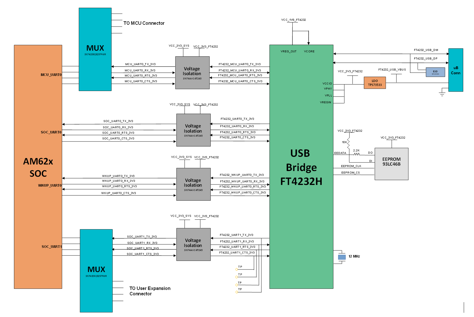
2.6.9 UART Interface
The four UART ports of the SoC (MCU UART0, WKUP UART0, SoC UART0 and SoC UART1) provided by the AM62x are interfaced with an FTDI FT4232HL for UART-to-USB functionality and terminated on a USB micro-B connector (J15) on board. When the AM62X SKEVM is connected to a Host using USB cable, the computer can establish a Virtual Com Port which can be used with any terminal emulation application. The FT4232HL is bus powered.
Since the circuit is powered through BUS power, the connection to the COM port will not be lost when the SKEVM power is removed.
| UART Port | USB to UART Bridge | USB Connector | COM Port |
|---|---|---|---|
| SoC_UART0 | FT4232HL |
J15 |
COM1 |
| SoC_UART1 | COM2 | ||
| WKUP_UART0 | COM3 | ||
| MCU_UART0 | COM4 |
The FT4232 chip is configured to operate in ‘Single chip USB to four channel UART’ mode and will take the configuration file from the external SPI EEPROM connected to it. The EEPROM (93LC46B) supports 1Mbit/s clock rate. The EEPROM is programmable in-circuit over USB using a utility program called FT_PROG available from FTDI's web site. The FT_PROG is also used for programming the board serial number for users to identify the connected COM port with board serial number when one or more boards are connected to the computer.