SPRUJ40C may 2022 – may 2023
- 1
- Abstract
- Trademarks
- 1EVM Revisions and Assembly Variants
-
2System Description
- 2.1 Key Features
- 2.2 Functional Block Diagram (SK-AM62 and SK-AM62B)
- 2.3 Functional Block Diagram (SK-AM62-P1 and SK-AM62B-P1)
- 2.4 AM62x SKEVM Interface Mapping
- 2.5 Power ON/OFF Procedures
- 2.6
Peripheral and Major Component
Description
- 2.6.1 Clocking
- 2.6.2 Reset
- 2.6.3 OLDI Display Interface
- 2.6.4 CSI Interface
- 2.6.5 Audio Codec Interface
- 2.6.6 HDMI Display Interface
- 2.6.7 JTAG Interface
- 2.6.8 Test Automation Header
- 2.6.9 UART Interface
- 2.6.10 USB Interface
- 2.6.11 Memory Interfaces
- 2.6.12 Ethernet Interface
- 2.6.13 GPIO Port Expander
- 2.6.14 GPIO Mapping
- 2.6.15 Power
- 2.6.16 AM62x SKEVM User Setup/Configuration
- 2.6.17 Expansion Headers
- 2.6.18 Interrupt
- 2.6.19 I2C Address Mapping
-
3Known Issues and Modifications
- 3.1 Issue 1 - HDMI/DSS Incorrect Colors on E1
- 3.2 Issue 2 - J9 and J10 Header Alignment on E1
- 3.3 Issue 3 - USB Boot descoped on E1
- 3.4 Issue 4 - OLDI Connector Orientation and Pinout
- 3.5 Issue 5 - Bluetooth descoped on E2 EVMs
- 3.6 Issue 6 - Ethernet PHY CLK Skew Default Strapping Changes
- 3.7 Issue 7 - TEST_POWERDOWN changes
- 3.8 Issue 8 - MMC1_SDCD spurious interrupts
- 3.9 Issue 9 - PD Controller I2C2 IRQ Not Pinned Out
- 3.10 Issue 10 - INA Current Monitor Adress Changes
- 3.11 Issue 11 - Test Automation I2C Buffer Changes
- Regulatory Compliance
- Revision History
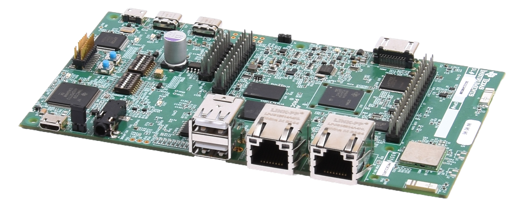
Abstract
This technical User’s Guide describes the hardware architecture of the AM62x SKEVM, a low cost Starter Kit built around the AM62x SoC. The AM62x processor comprises of a Quad-Core 64-bit Arm®-Cortex® A53 microprocessor, Single-core Arm Cortex-R5F MCU and an Arm Cortex-M4F MCU.
The SKEVM allows the user to experience great dual display feature through HDMI (over DPI) and LVDS, as well as industrial communication solutions using serial, Ethernet, USB and other interfaces.
The SKEVM can be used for your display application(for example a HMI or control panel) with either a HDMI display or an external LVDS panel, up to 2K resolution. It's high performance (up to) Quad-A53 ARM cores at 1.4GHz, with rich industrial interfaces, offer control and communication capabilities for a wide ranges of applications, such as PLC, automation control and monitor/supervisor systems. In addition, SKEVM can communicate with other processors or systems, and act as a communication gateway. The embedded emulation logic allows for emulation and debugging using standard development tools such as Code Composer Studio™ from TI.