SSZT324 march 2020 INA186-Q1 , INA190-Q1
Today’s vehicles have more intelligence and more connectivity than our mobile phones did 20 years ago. They are in near-constant communication with the world, whether through subscription-based communications services or built-in cellular functionality. In the future, this will include vehicle-to-vehicle communication. The core controlling communication to the outside world is the telematics control unit (TCU) (Figure 1).
 Figure 1 Typical Vehicle-to-world
Connectivity Options
Figure 1 Typical Vehicle-to-world
Connectivity OptionsIn addition to the communication that happens when the vehicle is in motion, there is a need to communicate when the vehicle is turned off, for tasks like module firmware downloads, diagnostic uploads to cloud services or location services notifications.
For internal combustion engine-based vehicles, vehicle-off communication will always be a drain on the battery. While this might not be a concern for a charging electric vehicle, a noncharging electric vehicle runs into the same issue as an internal combustion vehicle. Although communication will not consume nearly enough power to drain a battery, if the vehicle is in an extended off-state (such as parked at the airport during a long trip), the drain does potentially become a concern. Therefore, it is important to understand how much power is being consumed by this vehicle off communication to ensure that there will be enough battery power left to start the vehicle when the owner returns. The current consumed is often referred to as “dark current.”
Different vehicles have different methodologies for monitoring their dark-current consumption. Many vehicles simply count the number of communication sequences that have occurred. When the count reaches a certain level, the TCU will slow down the frequency of communication and eventually stop it all together to preserve the battery’s state of charge. This method works well if all communications have equal power consumption.
If on the other hand, different communications consume different current amounts, it may be more beneficial to measure the actual consumption to better know the current being drained from the battery. Measuring this current presents two primary challenges:
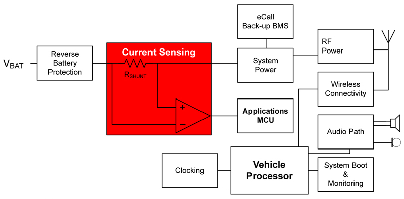
- The telematics system is most likely directly connected to the 12-V battery rail as shown in Figure 2, which for many vehicles requires 40 V of overvoltage survivability.
- The current levels that need to be measured are often in the tens of milliamperes. This presents a challenge for many current-measurement technologies, especially if they also have to measure normal current consumption levels that could be in the tens-of-ampere range.
 Figure 2 Typical System Block Diagram
for a TCU with Integrated eCall Functionality, Highlighting the Diagnostic
Current Monitoring of the 12-v Battery Input Line
Figure 2 Typical System Block Diagram
for a TCU with Integrated eCall Functionality, Highlighting the Diagnostic
Current Monitoring of the 12-v Battery Input LineTI’s INA186-Q1 addresses both challenges. The INA186-Q1 has a common-mode voltage range that extends up to 42 V, allowing it to survive on automotive 12-V battery rails. For more information on this topic, see the “12-V Battery Monitoring in an Automotive Module” application brief.
The ability to have a dynamic range of four decades of current measurement is a challenge for most current-sense amplifiers. For example, let’s say that you had these specifications:
- Bidirectional current measurement:
- Maximum measured current: ±10 A.
- Minimum measured current: ±10
mA.
- Common-mode voltage: 12 V (VBATT).
- Supply voltage: 5 V.
- INA186A1-Q1 with a gain of 25 V/V.
Thus, you have an output voltage swing that is approximately half of the supply voltage (2.46 V – see section 7.4.3 of the INA186-Q1 data sheet for more information on bidirectional current measurement). To calculate the ideal shunt resistor value, you would want 10 A to be exactly 2.46 V. At a gain of 25, this translates to an input voltage of 98.4 mV. Therefore, the ideal shunt value is 9.84 mΩ. In reality, you will want to use a slightly lower-valued shunt resistor to ensure that you do not saturate the output over various operating conditions and shunt variations.
The root-sum-square method is used for error calculation. TI offers more on current measurement error calculation in our TI Precision Labs - Current Sense Amplifiers training series – specifically the TI Precision Labs - Current Sense Amplifiers: Introduction to Different Error Sources video. A first-order calculation using these four error sources – offset, gain error, common-mode rejection and power-supply rejection – results in the error levels shown in Table 1 at the two extreme currents.
| Device | MaxVOUT (V) | Gain(V/V) | MaxVIN (V) | IdealRSHUNT (mΩ) | Errorat 0.01 A (%) | Errorat 10 A (%) |
|---|---|---|---|---|---|---|
| INA186A1-Q1 | 2.46 | 25 | 0.10 | 9.840 | 65.1% | 0.9% |
| INA190A1-Q1 | 2.46 | 25 | 0.10 | 9.840 | 21.9% | 0.2% |
As you can see, the error at 10 mA is over 50%, which may be too high for the application. To improve the error at low currents, you’ll need an amplifier with better offset. The INA190-Q1 shown in Table 1 is a pin-for-pin upgrade to the INA186-Q1 that provides improved accuracy.
In addition, you need to comprehend the power dissipation of the system and the cost of the shunt resistor. At a maximum current of 10 A with a 9.84-mΩ shunt, the maximum power dissipation is just under 1 W. If you can tolerate the additional low-current error, it will likely be easier to identify a cost-effective 4.92-mΩ shunt with 0.5-W power dissipation than the original 9.84-mΩ shunt. The low-current error will increase, however, with half of the voltage drop at minimum current.
As vehicle-off communications increase, it is vital to ensure that the battery will retain enough charge to handle vehicle-start functions. Accurately measuring the current consumed is one way to help the vehicle manage this functionality. TI current-sense amplifiers can help solve challenges related to high-accuracy dark-current monitoring.
Additional Resources:
- Read the application brief, “12-V Battery Monitoring in an Automotive Module.”
- Learn more about TI’s current sense amplifier portfolio.