SSZT592 november 2018 ISO1042 , ISO1042-Q1
With more and more of today’s systems operating at different voltages, isolated CAN transceivers have become integral in applications ranging from elevators to electric vehicles to even marine systems.
These transceivers help maintain reliable communication between two voltage domains in a system by combining the prioritization and arbitration features of the Controller Area Network (CAN) standard with the benefits of isolation (breaking ground loops, withstanding voltage differences, common-mode transient immunity, etc.).
As with non-isolated CAN systems, a key concern for those working with isolated CAN systems is the electromagnetic compatibility (EMC) performance of isolated CAN transceivers. EMC performance is measured through two parameters:
- Emissions produced by the devices
- Immunity from interference present in the system
Emissions
Emissions are the unintentional release of electromagnetic energy. Ideally, low emissions ensure reliable subsystem operation while at the same time not affecting the performance of adjacent subsystems.
Depending on the market (industrial or automotive) and application, systems must comply with different emissions standards. Even though emissions tests are performed at the system level, designers typically choose components that meet requirements at the component level. This helps ensure that the individual devices do not exceed the limits by themselves. System design and board layout also play an important role in the overall emissions performance of the systems. Among the various emissions tests, the Zwickau standard is a stringent test for automotive applications that characterizes the emissions performance of CAN transceivers.
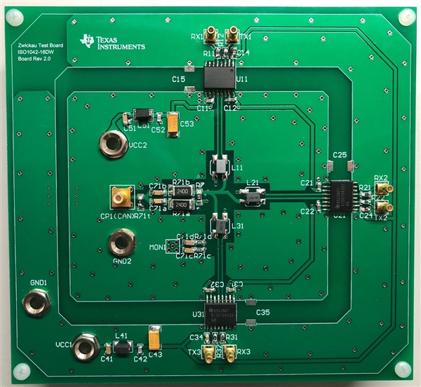
Figure 1 is an example of a board used for EMC testing. The board features three isolated CAN transceivers connected to the same bus. Emission measurements are taken at the test point (CP1 in Figure 1) while one transceiver transmits a 50% duty cycle, 250 kHz square wave signal.
 Figure 1 TI Board Used for EMC
Testing
Figure 1 TI Board Used for EMC
TestingPlacing common-mode chokes (CMC) between the transceivers and the bus filters out some of the emissions. The use of common-mode chokes is typical in automotive and industrial applications.
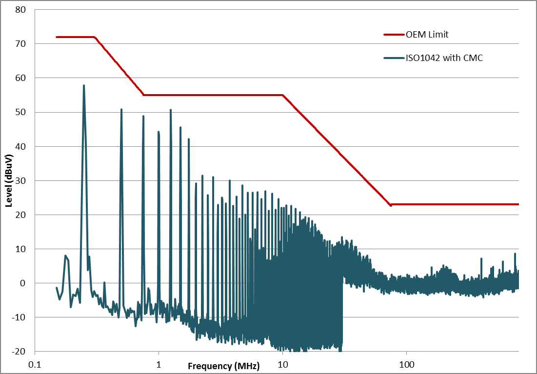
Conducted emissions data at classic CAN data rate using the ISO1042 on the EMC test board is shown in Figure 2.
 Figure 2 ISO1042 Conducted Emissions at
500Kbps
Figure 2 ISO1042 Conducted Emissions at
500KbpsCertain certification agencies require taking this data with the CMC, which also keeps emissions low. Under identical conditions, the ISO1042 outperformed competing devices in terms of emissions.
Immunity
Immunity is a device’s ability to function without error in the presence of interference. To demonstrate the noise immunity of isolated CAN devices, we performed a direct power injection (DPI) test on the same circuit shown in Figure 1, but with a different coupling network. The frequency of the noise injected on the bus was swept and the difference in the transmitted and received pattern was checked via a mask test. The noise signals injected for the test comprised a continuous wave (CW) noise signal and an amplitude modulated (AM) noise signal. The AM signal was an 80% 1-kHz signal. Variations more than a certain voltage limit (±0.9 V) vertically or a time limit (±0.2 µs) horizontally are considered a failure.
We performed the test under two different conditions:
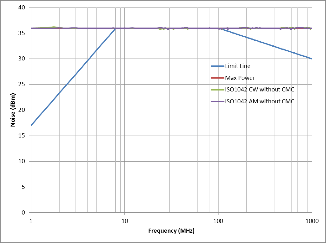
- 36 dBm of injected noise without a common-mode choke
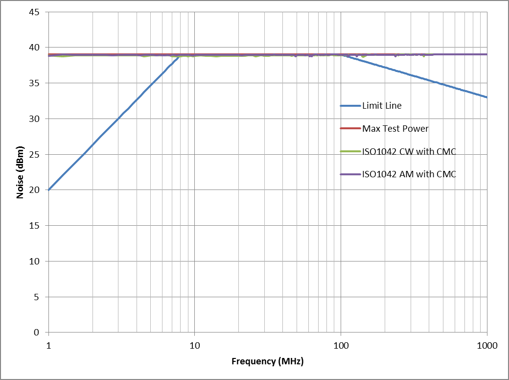
- 39 dBm noise signal in the presence of a common-mode choke
Figure 3 and Figure 4 show the ISO1042 plot under these two conditions for classic CAN. In both cases, the isolated CAN performance was above the limit lines, which indicated passing DPI tests. Passing these immunity tests ensures reliable communication with reduced system errors and failures.
 Figure 3 ISO1042 DPI Test without a
Common-mode Choke
 Figure 4 ISO1042 DPI Test with a
Common-mode Choke
Figure 4 ISO1042 DPI Test with a
Common-mode ChokeIntegrated isolated CAN devices are expected to meet the same emissions and immunity specifications as their non-isolated counterparts. Given their low emissions and high immunity in a small package, the ISO1042 and ISO1042-Q1 comply with the stringent requirements of industrial and automotive applications.
TI at Electronica
See a demo of the ISO1042 in action at the TI booth (Hall C4 – booth No. 131) at electronica at Messe München in Germany, Nov. 13-16, 2018 or watch a video of the demo, “the interoperability of isolated CAN FD nodes.”
Additional Resources
- Download the ISO1042 and ISO1042-Q1 data sheets.
- Watch the video, “key considerations for selecting isolated CAN transceivers.”
- Explore TI’s isolated CAN portfolio.