SSZTB78 june 2016 TPS65320-Q1 , TPS65320C-Q1
In recent years, automotive electronics have gained importance within automotive system design. You’ve most likely been hearing about the increase of convenience features, improved infotainment designs, driver assistance systems and growth in autonomous vehicle design. To drive innovation in automotive systems, every new device must be optimized for smaller and more stringent design requirements. What does this mean for the power tree that is supplying these applications?
In both parts of this two-part series, I will discuss how innovation has shifted the automotive electronic market and how TI has helped solve a common design challenge by integrating a buck converter and LDO together into one device.
Most automotive electronic control units (ECUs) require at least two regulated rails to efficiently power the system components. While both rails need to be present, their current requirements might differ significantly.
Take for example a light-emitting diode (LED) dome light with haptic feedback. The system requires a 5V rail to power the LED driver supplying the LEDs, and the haptics driver controlling the eccentric rotating mass (ERM) motor. The LED and the haptic drivers are current-intensive and require about 2A. A buck converter is the best option to provide this current due to the high efficiency required to keep a system cool at this load. The brain of an automotive ECU is a 3.3V microcontroller (MCU) with a low current demand of only 150mA. While the ECU can switch to standby mode to conserve power when the car ignition is turned off, the MCU may need to remain active to handle communication and wake-up functionality.
For these applications, you may select a low-dropout (LDO) regulator as the most cost-effective component to provide low current while delivering a clean power rail to the noise-sensitive microprocessor. But to support standby mode, the LDO is connected straight to the car battery, incurring a large voltage drop. Since that’s not the most efficient way to power the ECU, what can you do to optimize overall power consumption?
With the TPS65320C-Q1, you can supply a system like this straight from the battery. Supporting a Wide VIN range of 3.6V to 36V, the device provides two output rails: a 3.2A buck converter that supports switching frequencies from 100kHz to 2.5MHz at an accuracy of 10% and a 280mA LDO, both integrated in one small 14-pin HTSSOP.
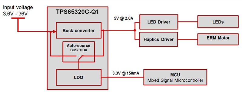
In the LED dome-light example, you would use the buck converter to power the 5V rail while the LDO takes care of the 3.3V rail, as shown in Figure 1. The integration of two rails on one chip allows a very small solution size and the addition of a feature that helps increase system efficiency: LDO auto-source. When the buck converter is enabled, the output of the switching regulator sources the LDO, minimizing the voltage drop, power consumption and thermal dissipation.
 Figure 1 Automotive Dome Light Block
Diagram in Active Mode
Figure 1 Automotive Dome Light Block
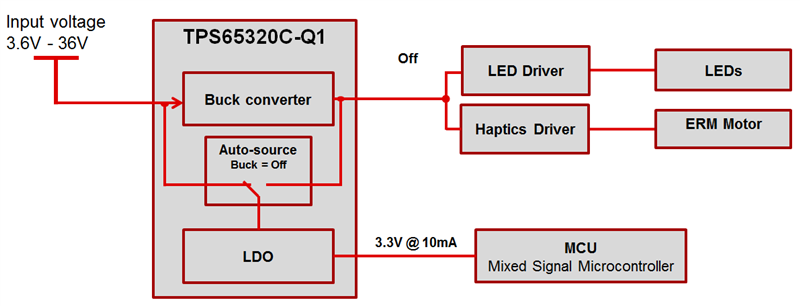
Diagram in Active ModeWhen the buck converter is deactivated, the LDO remains active and automatically switches its source to the battery voltage – allowing the MCU to remain active in standby mode while the rest of the system shuts off, with a typical quiescent current of less than 35µA from the LDO, as shown in Figure 2.
 Figure 2 Automotive Dome Light Block
Diagram in Standby Mode
Figure 2 Automotive Dome Light Block
Diagram in Standby ModeYou can find similar use cases in almost all automotive applications, including infotainment, advanced driver assistance systems (ADAS), cluster and body electronics.
Do you have the opposite requirement – requiring only 100mA at the 5V rail but 2A at the 3.3V rail? Stay tuned for part 2 of this series, when I’ll discuss using a wide VIN integrated buck and LDO to power your automotive system.
If you have questions about the LED dome light design or any other design considerations, login to post a comment below.
Additional Resources
- Read the TPS65320C-Q1 data sheet.
- Get started with the TPS65320EVM evaluation module.
- Download the TPS65320-Q1 Design Calculation Tool.