SSZTBB1 may 2016 LM3671 , LMZ20501
Back in the day, when board space was plentiful and mechanical enclosures were large, it was easy to just plop a low-dropout regulator (LDO) down on your printed circuit board (PCB), use extra copper, and add a heat sink to manage the heat. But in Industry 4.0 systems, that is not how it works. These smart systems use more sophisticated processors and require more power supplies in smaller enclosures with no airflow. Thus, it’s much more challenging to make the case for going back to that linear regulator you’ve been using for the past 10 years. You now need to consider more efficient power-supply techniques.
To increase system efficiency, you can either use LDOs or switching regulators. The efficiency of an LDO improves the closer the input voltage is to the output voltage. Switching regulators are specifically designed to boost efficiency, but require more design work and extra board space for the inductor.
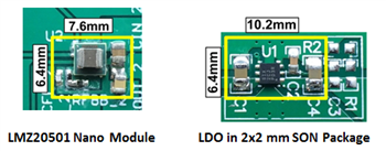
A new option on the market is an integrated inductor DC/DC converter that combines high-switching-frequency regulators with small-chip inductors. These integrated inductor DC/DC converters have the advantage of high switching frequencies with the ease of use of a linear regulator (see Figure 1).
 Figure 1 Solution Size of Nano Module
Compared to LDO
Figure 1 Solution Size of Nano Module
Compared to LDOLet’s say that you’re designing an industrial system that has no airflow and only 1in2 board space for each power supply. In this system, you need to power the auxiliary rail of an FPGA at a nominal 1.8V with a typical current requirement of 250mA from a 3.3V input voltage. A 500mA rated linear regulator in a modern small outline no-lead (SON) 3mm-by-3-mm package seems like the obvious choice, since the current requirement is low. The power dissipation in this application would be (Vin - Vo) x Io = (3.3V – 1.8V) x 250mA = 375mW. The SON 3mm-by-3-mm package has a 75°C/W temperature rise with a 1in2 copper board area. At 85°C ambient, the junction temperature of the integrated circuit (IC) would be Ta + Trise x Pd = 85°C + 75°C/W x 375mW = 107.5°C. A typical LDO with a maximum junction rating of 113°C is below the maximum junction temperature but does not give enough margin. You could add a heat sink or increase the copper area, but due to the mechanical requirements of your system, this is not an option.
At this point, your only option is to use a switching regulator. The LM3671 is a good option if you have the time to design a switching regulator. If not, consider an integrated inductor DC/DC converter like the LMZ20501 nano module. The LMZ20501 integrates the inductor in a 3.5-mm-by-3.5-mm package, so it is easy to use and small. The LMZ20501 provides 89% efficiency at 250mA output for 3.3V to 1.8V conversion. The LMZ20501 package has a 58°C/W temperature rise with 1in2 copper board area. At 85°C ambient, the IC junction temperature is only 88°C which is well below the maximum junction temperature.
Consider using an integrated inductor nano module for your next design. They are small, efficient and easy to use.
Additional Resources
- Watch a video with more examples of how an LDO compares to a nano module.
- Consider TI’s portfolio of modules for your next design.