SSZTBM6 February 2016 TMS320F28379D
Many industrial inverter and servo drive manufacturers have traditionally relied upon field-programmable gate-array (FPGA) or ASIC technology to complete functions that are not supported by commercial, off-the-shelf (COTS) products, like 32-bit microcontrollers (MCUs). However, adding FPGAs and ASICs to software programmable controllers, in order to support position sensor feedback or sigma-delta filtering, as examples, will increase system cost and add development complexity.
In this series of blogs we will take a look at the history of how industrial drive and servo control architectures have evolved, some of the challenges of introducing an FPGA into these architectures and how new capabilities of industrial drive control SoCs (COTS MCUs) shift the cost-benefit model away from using FPGAs in today’s industrial drives.
So how did FPGAs became common practice in inverter drive and servo control architectures? When new system functions were not achievable using the off-the-shelf controllers available at the time, many developers had to implement their specific PWM/IGBT protection scheme, for example, outside of the MCU. Others may have felt that their current loop timing was too short to be handled by a programmable MCU and that it could only be accomplished in logic gates vs. software. Once an FPGA is used in the system, it then becomes a bit of a system design crutch, albeit a logical crutch, to integrate support for the new technologies introduced by an evolving drives and servo market. For example, the FPGA functions expanded to integrate clockwise/counter-clockwise (CW/CCW) and pulse train output (PTO) ports for communications with PLCs and motion controllers. Next, FPGAs became the in-system destination for supporting emerging standard and proprietary position sensor interfaces like EnDat and BiSS. Further, the interfaces to the modulated outputs of isolated sigma-delta ADCs, typically based on sinc filters, were also integrated into the FPGA device. In addition, a few of the industrial Ethernet standards have made their MAC controllers available in FPGA gates as well. All of these different functions quickly add up to hundreds of thousands of gates and a very expensive FPGA.
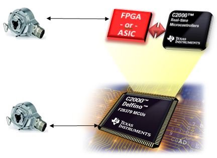
 Figure 1 SoC vs. MCU plus FPGA
Architectures
Figure 1 SoC vs. MCU plus FPGA
ArchitecturesWhile this expansion of drive functions was being absorbed by the FPGA, an interesting new market dynamic was also taking place. Catalog controllers started bringing these functions on-chip delivering off-the-shelf features for any drive developer to use. The difference here is substantial: The on-chip functions are available for the developer to use immediately – that is, to purchase an MCU available in a catalog without the need to construct these solutions using an FPGA. This correlates directly as a decrease in system cost and board space savings that are not possible with an FPGA solution. With the birth of new drive control SoCs, like C2000™ F28379 MCUs with DesignDRIVE Position Manager technology, developers can now avoid the many drawbacks cited above.
In the next part in this series we will dig a bit deeper into some of the other challenges associated with bringing FPGAs into drives and servo control architectures.