SWRA779 September 2023 CC3300 , CC3301
3.4.3 UART Flow Control
The universal asynchronous receiver-transmitter (UART) is a transport protocol that transfers a byte of data as a stream of individual bits in a sequential fashion. At the destination, a second UART re-assembles the bits into complete bytes. The UART is composed of four lines for data transmission (Tx), data reception (Rx), flow control holding the host transmissions (RTS) and flow control holding the device transmissions (CTS).
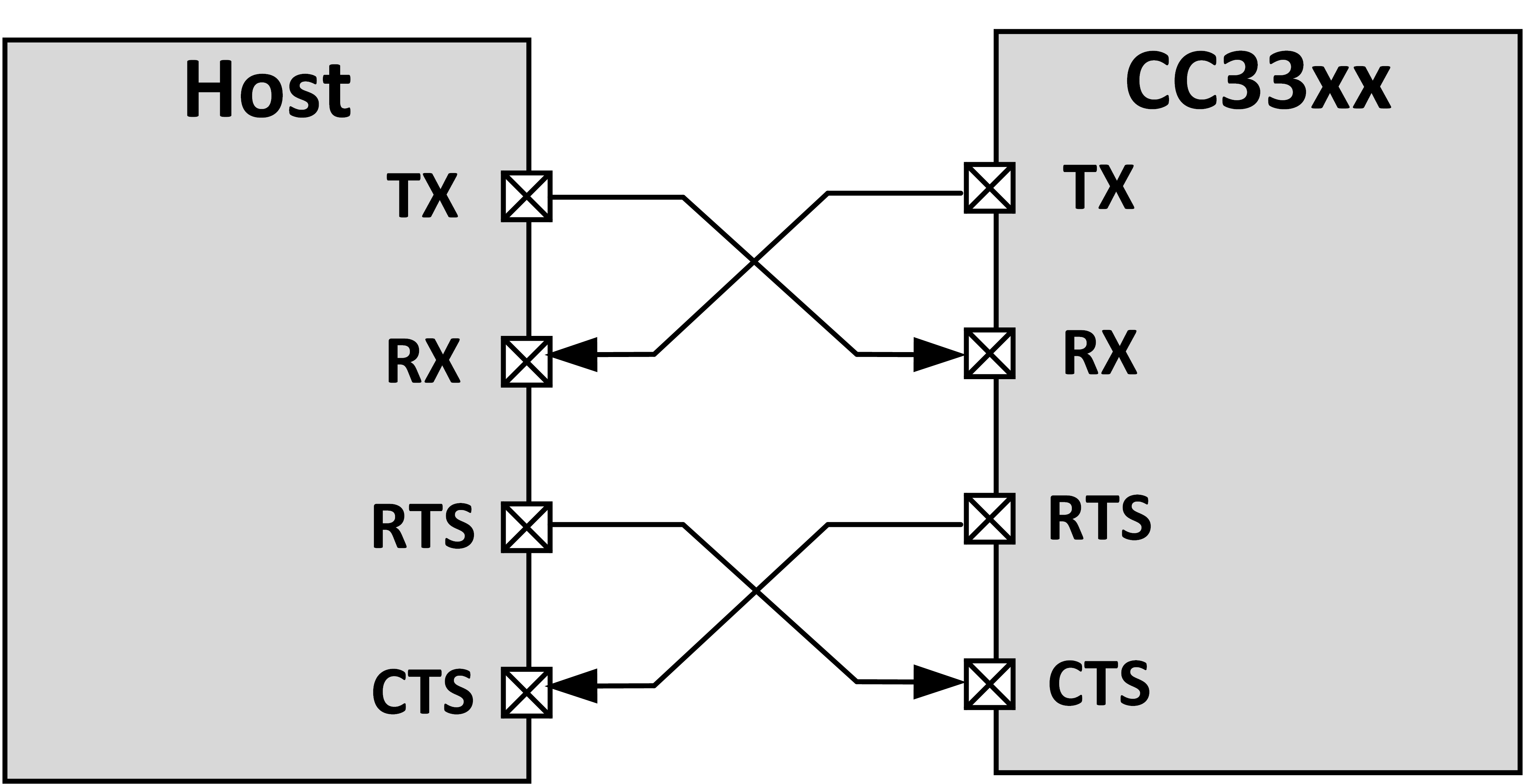
In UART interface there is no Controller/Peripheral relationship defined by the Hardware and each entity can send data to the other side independently in full duplex mode. The hardware flow control makes use of two hardware lines, RTS (Request to Send) and CTS (Clear to Send) to allow each side to indicate to the other side when it is ready to handle data. These wires are cross-coupled between the two devices, so RTS on one device is connected to CTS on the other device and vice versa. Each device uses its RTS to output if it is ready to accept new data and read CTS to see if it is allowed to send data to the other device.
As long as a device is ready to accept more data, it will keep the RTS line asserted. It will de-assert RTS some time before its receive buffer is full. There might still be data on the line and in the other device transmit registers that has to be received even after RTS has been de-asserted (in this case, the device finishes transmitting the byte and stops the transmission). The other device is required to respect the flow control signal and pause the transmission until RTS is again asserted.
Figure 3-5 illustrates the host and device hardware connectivity.
 Figure 3-5 UART Interface Flow
Control