SNVS440B May 2007 – March 2016 LP5520
PRODUCTION DATA.
- 1 Features
- 2 Applications
- 3 Description
- 4 Revision History
- 5 Pin Configuration and Function
-
6 Specifications
- 6.1 Absolute Maximum Ratings
- 6.2 ESD Ratings
- 6.3 Recommended Operating Conditions
- 6.4 Thermal Information
- 6.5 Electrical Characteristics
- 6.6 RGB Driver Electrical Characteristics (ROUT, GOUT, BOUT Outputs)
- 6.7 Logic Interface Characteristics
- 6.8 Magnetic Boost DC-DC Converter Electrical Characteristics
- 6.9 I2C Timing Parameters
- 6.10 SPI Timing Requirements
- 6.11 Typical Characteristics
- 7 Detailed Description
- 8 Application and Implementation
- 9 Power Supply Recommendations
- 10Layout
- 11Device and Documentation Support
- 12Mechanical, Packaging, and Orderable Information
Package Options
Mechanical Data (Package|Pins)
- YZR|25
Thermal pad, mechanical data (Package|Pins)
Orderable Information
1 Features
- Temperature Compensated LED Intensity and Color
- Individual Calibration Coefficients for Each Color
- Color Accuracy ΔX and ΔY ≤ 0.003
- 12-Bit ADC for Measurement of 2 Sensors
- Adjustable Current Outputs for Red, Green, and Blue (RGB) LED
- 0.2% Typical LED Output Current Matching
- PWM Control Inputs for Each Color
- SPI™ and I2C-Compatible Interface
- Stand-Alone Mode With One-Wire Control
- Sequential Mode for One Color at a Time
- Magnetic High Efficiency Boost Converter
- Programmable Output Voltage from 5 V to 20 V
- Adaptive Output Voltage Control Option
- < 2-µA Typical Shutdown Current
3 Description
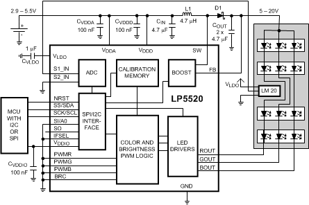
The LP5520 is an RGB backlight LED driver for small format color LCDs. RGB backlights enable better colors on the display and power savings compared with white LED backlights. The device offers a small and simple driver solution without need for optical feedback. Calibration in display module production can be done in one temperature. The LP5520 produces true white light over a wide temperature range. Three independent LED drivers have accurate programmable current sinks and PWM modulation control. Using internal calibration memory and external temperature sensor, the RGB LED currents are adjusted for perfect white balance independent of the brightness setting or temperature. The user programmable calibration memory has intensity vs temperature data for each color. This white balance calibration data can be programmed to the memory on the production line of a backlight module.
The device has a magnetic boost converter that creates a supply voltage of up to 20 V LED from the battery voltage. The output can be set at 1-V steps from 5 V to 20 V. In adaptive mode the circuit automatically adjusts the output voltage to minimum sufficient level for lowest power consumption. Temperature is measured using an external temperature sensor placed close to the LEDs. The second ADC input can be used, for example, for ambient light measurement.
Device Information(1)
| PART NUMBER | PACKAGE | BODY SIZE (MAX) |
|---|---|---|
| LP5520 | DSBGA (25) | 2.787 mm × 2.621 mm |
Typical Application
