SLUSC23 September 2015
PRODUCTION DATA.
- 1 Features
- 2 Applications
- 3 Description
- 4 Simplified Schematic
- 5 Revision History
- 6 Pin Configuration and Functions
-
7 Specifications
- 7.1 Absolute Maximum Ratings
- 7.2 ESD Ratings
- 7.3 Recommended Operating Conditions
- 7.4 Supply Current
- 7.5 Power Supply Control
- 7.6 Low-Voltage General Purpose I/O, TS1
- 7.7 Power-On Reset (POR)
- 7.8 Internal 1.8-V LDO
- 7.9 Current Wake Comparator
- 7.10 Coulomb Counter
- 7.11 ADC Digital Filter
- 7.12 ADC Multiplexer
- 7.13 Cell Balancing Support
- 7.14 Internal Temperature Sensor
- 7.15 NTC Thermistor Measurement Support
- 7.16 High-Frequency Oscillator
- 7.17 Low-Frequency Oscillator
- 7.18 Voltage Reference 1
- 7.19 Voltage Reference 2
- 7.20 Instruction Flash
- 7.21 Data Flash
- 7.22 Current Protection Thresholds
- 7.23 Current Protection Timing
- 7.24 N-CH FET Drive (CHG, DSG)
- 7.25 I2C and HDQ Interface I/O
- 7.26 I2C Interface Timing
- 7.27 HDQ Interface Timing
- 7.28 Typical Characteristics
-
8 Detailed Description
- 8.1 Overview
- 8.2 Functional Block Diagram
- 8.3
Feature Description
- 8.3.1 Battery Parameter Measurements
- 8.3.2 Coulomb Counter (CC)
- 8.3.3 CC Digital Filter
- 8.3.4 ADC Multiplexer
- 8.3.5 Analog-to-Digital Converter (ADC)
- 8.3.6 ADC Digital Filter
- 8.3.7 Internal Temperature Sensor
- 8.3.8 External Temperature Sensor Support
- 8.3.9 Power Supply Control
- 8.3.10 Power-On Reset
- 8.3.11 Bus Communication Interface
- 8.3.12 Cell Balancing Support
- 8.3.13 N-Channel Protection FET Drive
- 8.3.14 Low Frequency Oscillator
- 8.3.15 High Frequency Oscillator
- 8.3.16 1.8-V Low Dropout Regulator
- 8.3.17 Internal Voltage References
- 8.3.18 Overcurrent in Discharge Protection
- 8.3.19 Short-Circuit Current in Charge Protection
- 8.3.20 Short-Circuit Current in Discharge 1 and 2 Protection
- 8.3.21 Primary Protection Features
- 8.3.22 Gas Gauging
- 8.3.23 Charge Control Features
- 8.3.24 Authentication
- 8.4 Device Functional Modes
- 9 Applications and Implementation
- 10Power Supply Requirements
- 11Layout
- 12Device and Documentation Support
- 13Mechanical, Packaging, and Orderable Information
Package Options
Mechanical Data (Package|Pins)
- DRZ|12
Thermal pad, mechanical data (Package|Pins)
Orderable Information
9 Applications and Implementation
9.1 Application Information
NOTE
Information in the following applications sections is not part of the TI component specification, and TI does not warrant its accuracy or completeness. TI’s customers are responsible for determining suitability of components for their purposes. Customers should validate and test their design implementation to confirm system functionality.
The bq78z100 gas gauge is a primary protection device that can be used with a 1-series or 2-series Li-Ion/Li Polymer battery pack. To implement and design a comprehensive set of parameters for a specific battery pack, the user needs Battery Management Studio (bqSTUDIO), which is a graphical user-interface tool installed on a PC during development. The firmware installed in the product has default values, which are summarized in the bq78z100 Technical Reference Manual (SLUUB63) for this product. Using the bqSTUDIO tool, these default values can be changed to cater to specific application requirements during development once the system parameters, such as fault trigger thresholds for protection, enable/disable of certain features for operation, configuration of cells, chemistry that best matches the cell used, and more are known. This data can be referred to as the "golden image."
9.2 Typical Applications
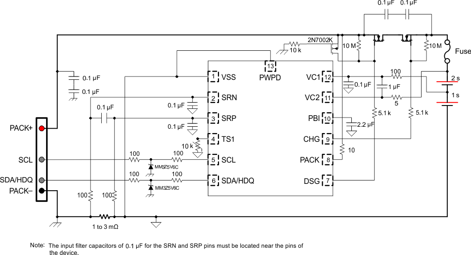
The following is the bq78z100 application schematic for the 2-series configuration.
 Figure 22. bq78z100 2-Series Cell Typical Implementation
9.2.1 Design Requirements (Default)
| Design Parameter | Example |
|---|---|
| Cell Configuration | 2s1p (2-series with 1 Parallel) |
| Design Capacity | 4400 mAH |
| Device Chemistry | 100 (LiCoO2/graphitized carbon) |
| Cell Overvoltage at Standard Temperature | 4300 mV |
| Cell Undervoltage | 2500 mV |
| Shutdown Voltage | 2300 mV |
| Overcurrent in CHARGE Mode | 6000 mA |
| Overcurrent in DISCHARGE Mode | –6000 mA |
| Short Circuit in CHARGE Mode | 0.1 V/Rsense across SRP, SRN |
| Short Circuit in DISCHARGE 1 Mode | 0.1 V/Rsense across SRP, SRN |
| Safety Over Voltage | 4500 mV |
| Cell Balancing | Disabled |
| Internal and External Temperature Sensor | Enabled |
| Under Temperature Charging | 0°C |
| Under Temperature Discharging | 0°C |
| BROADCAST Mode | Enabled |
| I2C Interface | Enabled |
9.2.2 Detailed Design Procedure
9.2.2.1 Setting Design Parameters
For the firmware settings needed for the design requirements, refer to the bq78z100 Technical Reference Manual (SLUUB63).
- To set the 2s1p battery pack, go to data flash Configuration: DA Configuration register's bit 0 (CC0) = 1.
- To set design capacity, set the data flash value to 4400 in the Gas Gauging: Design: Design Capacity register.
- To set device chemistry, go to data flash SBS Configuration: Data: Device Chemistry. The bqStudio software automatically populates the correct chemistry identification. This selection is derived from using the bqCHEM feature in the tools and choosing the option that matches the device chemistry from the list.
- To protect against cell overvoltage, set the data flash value to 4300 in Protections: COV: Standard Temp.
- To protect against cell undervoltage, set the data flash value to 2500 in the Protections: CUV register.
- To set the shutdown voltage to prevent further pack depletion due to low pack voltage, program Power: Shutdown: Shutdown voltage = 2300.
- To protect against large charging currents when the AC adapter is attached, set the data flash value to 6000 in the Protections: OCC: Threshold register.
- To protect against large discharging currents when heavy loads are attached, set the data flash value to –6000 in the Protections: OCD: Threshold register.
- Program a short circuit delay timer and threshold setting to enable the operating the system for large short transient current pulses. These two parameters are under Protections: ASCC: Threshold = 100 for charging current. The discharge current setting is Protections: ASCD:Threshold = –100 mV.
- To prevent the cells from overcharging and adding a second level of safety, there is a register setting that will shut down the device if any of the cells voltage measurement is greater than the Safety Over Voltage setting for greater than the delay time. Set this data flash value to 4500 in Permanent Fail: SOV: Threshold.
- To disable the cell balancing feature, set the data flash value to 0 in Settings: Configuration: Balancing Configuration: bit 0 (CB).
- To enable the internal temperature and the external temperature sensors: Set Settings:Configuration: Temperature Enable: Bit 0 (TSInt) = 1 for the internal sensor; set Bit 1 (TS1) = 1 for the external sensor.
- To prevent charging of the battery pack if the temperature falls below 0°C, set Protections: UTC:Threshold = 0.
- To prevent discharging of the battery pack if the temperature falls below 0°C, set Protections: UTD:Threshold = 0.
Each parameter listed for fault trigger thresholds has a delay timer setting associated for any noise filtering. These values, along with the trigger thresholds for fault detection, may be changed based upon the application requirements using the data flash settings in the appropriate register stated in the bq78z100 Technical Reference Manual (SLUUB63).
9.2.3 Calibration Process
The calibration of Current, Voltage, and Temperature readings is accessible by writing 0xF081 or 0xF082 to ManufacturerAccess(). A detailed procedure is included in the bq78z100 Technical Reference Manual (SLUUB63) in the Calibration section. The description allows for calibration of Cell Voltage Measurement Offset, Battery Voltage, Pack Voltage, Current Calibration, Coulomb Counter Offset, PCB Offset, CC Gain/Capacity Gain, and Temperature Measurement for both internal and external sensors.
9.2.4 Gauging Data Updates
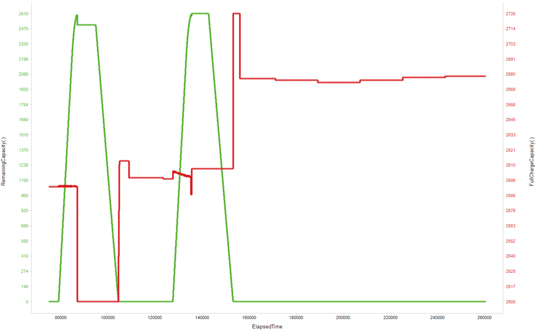
When a battery pack enabled with the bq78z100 is first cycled, the value of FullChargeCapacity() updates several times. Figure 23 shows RemainingCapacity() and FullChargeCapacity(), and where those updates occur. As part of the Impedance Track algorithm, it is expected that FullChargeCapacity() may update at the end of charge, at the end of discharge, and at rest.
9.2.4.1 Application Curve
 Figure 23. Gauging Data Updates