SLAS901C December 2016 – January 2021 HD3SS213
PRODUCTION DATA
- 1 Features
- 2 Applications
- 3 Description
- 4 Revision History
- 5 Pin Configuration and Functions
- 6 Specifications
- 7 Detailed Description
- 8 Application and Implementation
- 9 Layout
- 10Device and Documentation Support
- 11Mechanical, Packaging, and Orderable Information
Package Options
Mechanical Data (Package|Pins)
- ZXH|50
Thermal pad, mechanical data (Package|Pins)
Orderable Information
3 Description
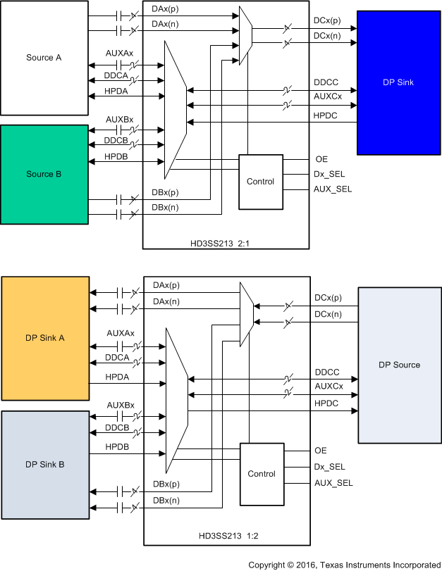
The HD3SS213 device is a high-speed passive switch capable of switching two full DisplayPort 4 lane ports from one of two sources to one target location in an application. It also switches one source to one of two sinks. For DisplayPort applications, the HD3SS213 supports switching of the Auxiliary (AUX), Display Data Channel (DDC), and Hot Plug Detect (HPD) signals in the ZEQ package.
One typical application is a mother board that includes two GPUs that need to drive one DisplayPort sink. The GPU is selected by the Dx_SEL pin. Another application is when one source needs to switch between one of two sinks which the example is a side connector and a docking station connector. The switching is controlled using the Dx_SEL and AUX_SEL pins. The HD3SS213 operates from a single supply voltage of 3.3 V over the full industrial temperature range of –40°C to 105°C.
| PART NUMBER | PACKAGE | BODY SIZE (NOM) |
|---|---|---|
| HD3SS213 | nFBGA (50) | 5.00 mm x 5.00 mm |
 HD3SS213 Application Block Diagram