SBOS792A August 2017 – January 2018 INA828
PRODUCTION DATA.
- 1 Features
- 2 Applications
- 3 Description
- 4 Revision History
- 5 Pin Configuration and Functions
- 6 Specifications
- 7 Detailed Description
- 8 Application and Implementation
- 9 Power Supply Recommendations
- 10Layout
- 11Device and Documentation Support
- 12Mechanical, Packaging, and Orderable Information
Package Options
Mechanical Data (Package|Pins)
- D|8
Thermal pad, mechanical data (Package|Pins)
Orderable Information
7.3.2 EMI Rejection
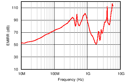
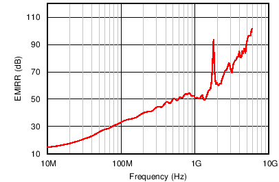
Texas Instruments developed a method to accurately measure the immunity of an amplifier over a broad frequency spectrum, extending from 10 MHz to 6 GHz. This method uses an EMI rejection ratio (EMIRR) to quantify the ability of the INA828 to reject EMI. The offset resulting from an input EMI signal can be calculated using Equation 2:

where
- VRF_PEAK is the peak amplitude of the input EMI signal.
Figure 53 and Figure 54 show the INA828 EMIRR graph for both differential and common-mode EMI rejection across this frequency range. Table 2 shows the EMIRR values for the INA828 at frequencies commonly encountered in real-world applications. Applications listed in Table 2 can be centered on or operated near the particular frequency shown. Depending on the end-system requirements, additional EMI filters may be required near the signal inputs of the system, as well as incorporating known good practices such as using short traces, low-pass filters, and damping resistors combined with parallel and shielded signal routing.


Table 2. INA828 EMIRR for Frequencies of Interest
| FREQUENCY | APPLICATION OR ALLOCATION | DIFFERENTIAL EMIRR | COMMON-MODE EMIRR |
|---|---|---|---|
| 400 MHz | Mobile radio, mobile satellite, space operation, weather, radar, ultrahigh-frequency (UHF) applications | 48 dB | 87 dB |
| 900 MHz | Global system for mobile communications (GSM) applications, radio communication, navigation, GPS (up to 1.6 GHz), GSM, aeronautical mobile, UHF applications | 52 dB | 98 dB |
| 1.8 GHz | GSM applications, mobile personal communications, broadband, satellite, L-band (1 GHz to 2 GHz) |
94 dB | 51 dB |
| 2.4 GHz | 802.11b, 802.11g, 802.11n, Bluetooth®, mobile personal communications, industrial, scientific and medical (ISM) radio band, amateur radio and satellite, S-band (2 GHz to 4 GHz) | 66 dB | 57 dB |
| 3.6 GHz | Radiolocation, aero communication and navigation, satellite, mobile, S-band | 79 dB | 87 dB |
| 5 GHz | 802.11a, 802.11n, aero communication and navigation, mobile communication, space and satellite operation, C-band (4 GHz to 8 GHz) | 90 dB | 92 dB |