SLOS580H may 2008 – august 2023 ISO15 , ISO35
PRODUCTION DATA
- 1
- 1 Features
- 2 Applications
- 3 Description
- 4 Revision History
- 5 Pin Configuration and Functions
-
6 Specifications
- 6.1 Absolute Maximum Ratings
- 6.2 ESD Ratings
- 6.3 Recommended Operating Conditions
- 6.4 Thermal Information
- 6.5 Power Ratings
- 6.6 Insulation Specifications
- 6.7 Safety-Related Certifications
- 6.8 Safety Limiting Values
- 6.9 Electrical Characteristics: Driver
- 6.10 Electrical Characteristics: Receiver
- 6.11 Supply Current
- 6.12 Switching Characteristics: Driver
- 6.13 Switching Characteristics: Receiver
- 6.14 Insulation Characteristics Curves
- 6.15 Typical Characteristics
- 7 Parameter Measurement Information
- 8 Detailed Description
- 9 Application and Implementation
- Power Supply Recommendations
- 10Layout
- 11Device and Documentation Support
- 13Mechanical, Packaging, and Orderable Information
Package Options
Mechanical Data (Package|Pins)
- DW|16
Thermal pad, mechanical data (Package|Pins)
- DW|16
Orderable Information
3 Description
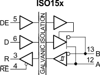
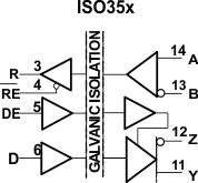
The ISO15 is an isolated half-duplex differential line transceiver while the ISO35 is an isolated full-duplex differential line driver and receiver for TIA/EIA 485/422 applications. The ISO15M and ISO35M have extended ambient temperature ratings of –55°C to 125°C while the ISO15 and ISO35 are specified over –40°C to 85°C.
These devices are ideal for long transmission lines because the ground loop is broken to allow for a much larger common-mode voltage range. The symmetrical barrier of the device is tested to provide isolatlion of 4000 VPK per VDE and 2500 VRMS per UL and CSA between the bus-line transceiver and the logic-level interface.
Any cabled I/O can be subjected to electrical noise transients from various sources. These noise transients can cause damage to the transceiver and/or nearby sensitive circuitry if they are of sufficient magnitude and duration. These isolated devices can significantly increase protection and reduce the risk of damage to expensive control circuits.
| PART NUMBER | PACKAGE | BODY SIZE (NOM) |
|---|---|---|
| ISO15 | SOIC (16) | 10.30 mm × 7.50 mm |
| ISO35 |
 Simplified Schematic