SNIS160E May 1999 – February 2015 LM135 , LM135A , LM235 , LM235A , LM335 , LM335A
PRODUCTION DATA.
- 1 Features
- 2 Applications
- 3 Description
- 4 Revision History
- 5 Pin Configuration and Functions
- 6 Specifications
- 7 Detailed Description
- 8 Application and Implementation
- 9 Power Supply Recommendations
- 10Layout
- 11Device and Documentation Support
- 12Mechanical, Packaging, and Orderable Information
Package Options
Mechanical Data (Package|Pins)
- NDV|3
Thermal pad, mechanical data (Package|Pins)
Orderable Information
6 Specifications
6.1 Absolute Maximum Ratings
over operating free-air temperature range (unless otherwise noted)(1)(3)(2)(4)| MIN | MAX | UNIT | ||
|---|---|---|---|---|
| Reverse Current | 15 | mA | ||
| Forward Current | 10 | mA | ||
| Storage temperature, Tstg | 8-Pin SOIC Package | −65 | 150 | °C |
| TO / TO-92 Package | −60 | 150 | °C | |
(1) Stresses beyond those listed under Absolute Maximum Ratings may cause permanent damage to the device. These are stress ratings only, which do not imply functional operation of the device at these or any other conditions beyond those indicated under Recommended Operating Conditions. Exposure to absolute-maximum-rated conditions for extended periods may affect device reliability.
(2) If Military/Aerospace specified devices are required, please contact the TI Sales Office/Distributors for availability and specifications.
(3) Refer to RETS135H for military specifications.
(4) Soldering process must comply with the Reflow Temperature Profile specifications. Refer to http://www.ti.com/packaging.
6.2 Recommended Operating Conditions
over operating free-air temperature range (unless otherwise noted)| MIN | NOM | MAX | UNIT | |||
|---|---|---|---|---|---|---|
| Specified Temperature | LM135, LM135A | Continuous (TMIN ≤ TA ≤ TMAX) | −55 | 150 | °C | |
| Intermittent (1) | 150 | 200 | ||||
| LM235, LM235A | Continuous (TMIN ≤ TA ≤ TMAX) | −40 | 125 | °C | ||
| Intermittent (1) | 125 | 150 | ||||
| LM335, LM335A | Continuous (TMIN ≤ TA ≤ TMAX) | −40 | 100 | °C | ||
| Intermittent (1) | 100 | 125 | ||||
| Forward Current | 0.4 | 1 | 5 | mA | ||
(1) Continuous operation at these temperatures for 5,000 hours for LP package may decrease life expectancy of the device.
6.3 Thermal Information
| THERMAL METRIC(1) | LM335 / LM335A | LM235 / LM235A | LM135 / LM135A | UNIT | |
|---|---|---|---|---|---|
| SOIC (D) | TO-92 (LP) | TO-46 (NDV) | |||
| 8 PINS | 3 PINS | 3 PINS | |||
| RθJA | Junction-to-ambient thermal resistance | 165 | 202 | 400 | °C/W |
| RθJC | Junction-to-case thermal resistance | — | 170 | — | |
(1) For more information about traditional and new thermal metrics, see the IC Package Thermal Metrics application report, SPRA953.
6.4 Temperature Accuracy: LM135/LM235, LM135A/LM235A(1)
| PARAMETER | TEST CONDITIONS | LM135A/LM235A | LM135/LM235 | UNIT | |||||
|---|---|---|---|---|---|---|---|---|---|
| MIN | TYP | MAX | MIN | TYP | MAX | ||||
| Operating Output Voltage | TC = 25°C, IR = 1 mA | 2.97 | 2.98 | 2.99 | 2.95 | 2.98 | 3.01 | V | |
| Uncalibrated Temperature Error | TC = 25°C, IR = 1 mA | 0.5 | 1 | 1 | 3 | °C | |||
| Uncalibrated Temperature Error | TMIN ≤ TC ≤ TMAX, IR = 1 mA | 1.3 | 2.7 | 2 | 5 | °C | |||
| Temperature Error with 25°C | TMIN ≤ TC ≤ TMAX, IR = 1 mA | 0.3 | 1 | 0.5 | 1.5 | °C | |||
| Calibration | Calibrated Error at Extended | TC = TMAX (Intermittent) | 2 | 2 | °C | ||||
| Temperature | Non-Linearity | IR = 1 mA | 0.3 | 0.5 | 0.3 | 1 | °C | ||
6.5 Temperature Accuracy: LM335, LM335A(1)
| PARAMETER | TEST CONDITIONS | LM335A | LM335 | UNIT | |||||
|---|---|---|---|---|---|---|---|---|---|
| MIN | TYP | MAX | MIN | TYP | MAX | ||||
| Operating Output Voltage | TC = 25°C, IR = 1 mA | 2.95 | 2.98 | 3.01 | 2.92 | 2.98 | 3.04 | V | |
| Uncalibrated Temperature Error | TC = 25°C, IR = 1 mA | 1 | 3 | 2 | 6 | °C | |||
| Uncalibrated Temperature Error | TMIN ≤ TC ≤ TMAX, IR = 1 mA | 2 | 5 | 4 | 9 | °C | |||
| Temperature Error with 25°C | TMIN ≤ TC ≤ TMAX, IR = 1 mA | 0.5 | 1 | 1 | 2 | °C | |||
| Calibration | Calibrated Error at Extended | TC = TMAX (Intermittent) | 2 | 2 | °C | ||||
| Temperature | Non-Linearity | IR = 1 mA | 0.3 | 1.5 | 0.3 | 1.5 | °C | ||
6.6 Electrical Characteristics
See (1).| PARAMETER | TEST CONDITIONS | LM135/LM235/LM135A/LM235A | LM335/LM335A | UNIT | ||||
|---|---|---|---|---|---|---|---|---|
| MIN | TYP | MAX | MIN | TYP | MAX | |||
| Operating Output Voltage Change with Current | 400 μA ≤ IR ≤ 5 mA, At Constant Temperature | 2.5 | 10 | 3 | 14 | mV | ||
| Dynamic Impedance | IR = 1 mA | 0.5 | 0.6 | Ω | ||||
| Output Voltage Temperature Coefficient | 10 | 10 | mV/°C | |||||
| Time Constant | Still Air | 80 | 80 | sec | ||||
| 100 ft/Min Air | 10 | 10 | sec | |||||
| Stirred Oil | 1 | 1 | sec | |||||
| Time Stability | TC = 125°C | 0.2 | 0.2 | °C/khr | ||||
(1) Accuracy measurements are made in a well-stirred oil bath. For other conditions, self heating must be considered.
6.7 Typical Characteristics
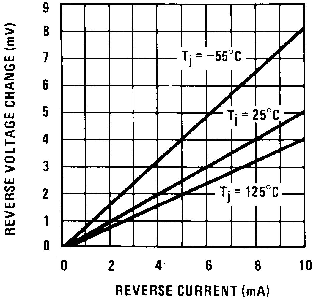 Figure 1. Reverse Voltage Change
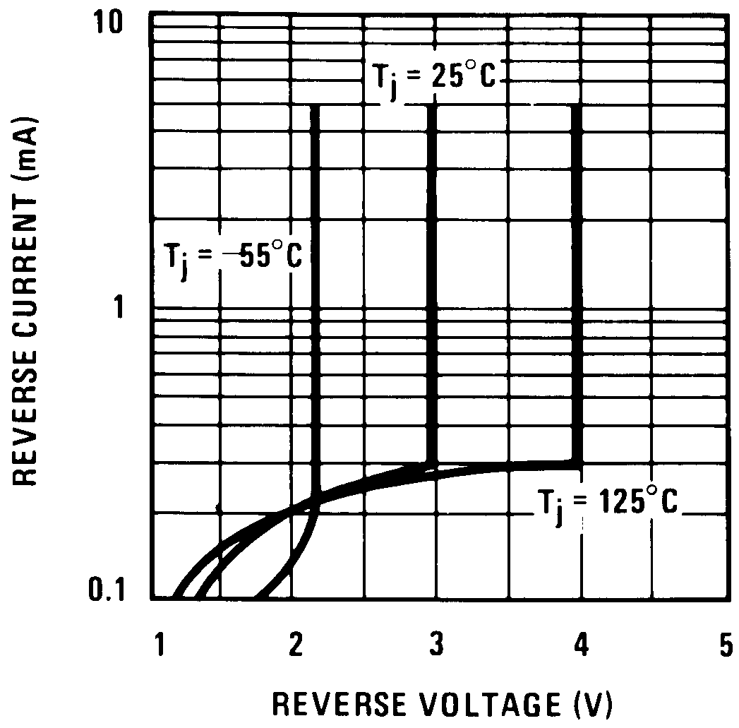 Figure 3. Reverse Characteristics
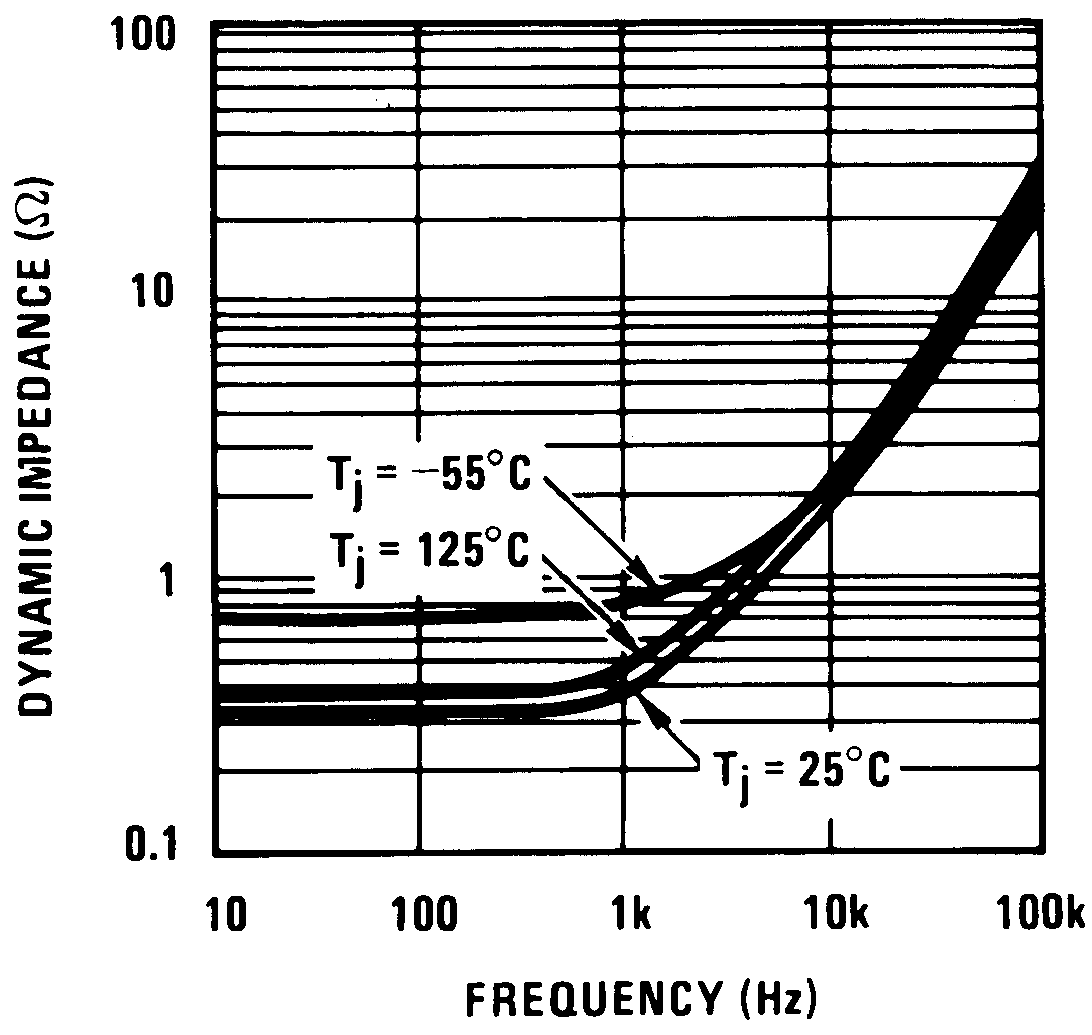 Figure 5. Dynamic Impedance
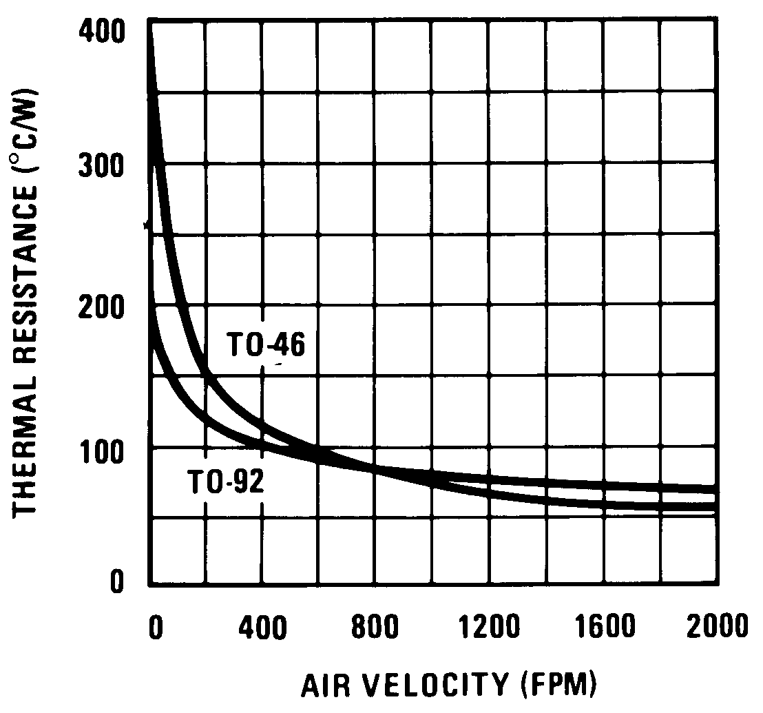 Figure 7. Thermal Resistance Junction To Air
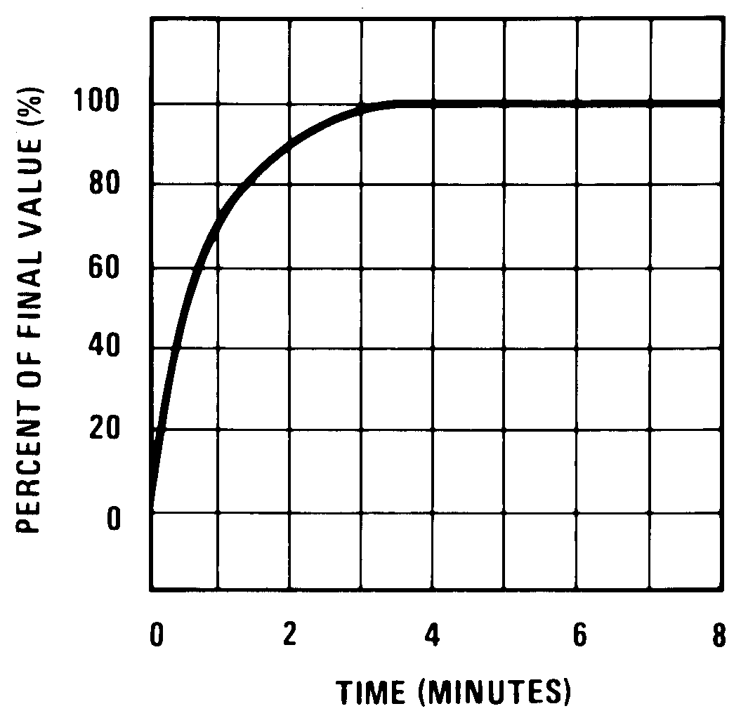 Figure 9. Thermal Response In Still Air
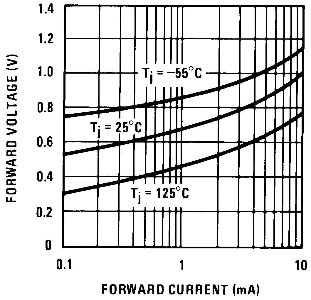 Figure 11. Forward Characteristics
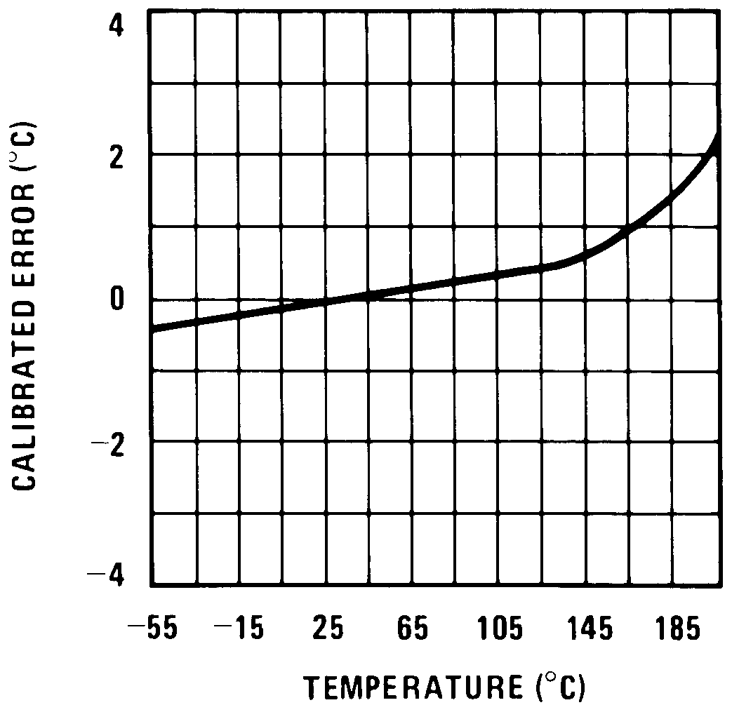 Figure 2. Calibrated Error
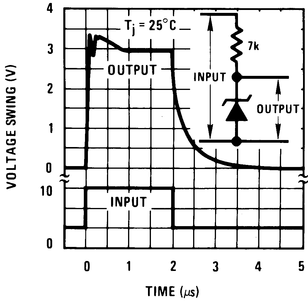 Figure 4. Response Time
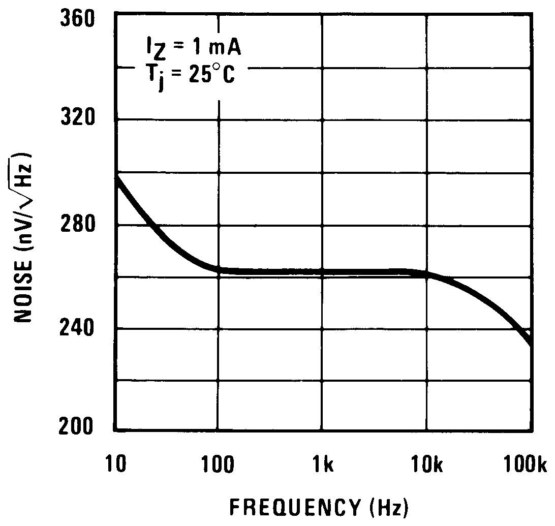 Figure 6. Noise Voltage
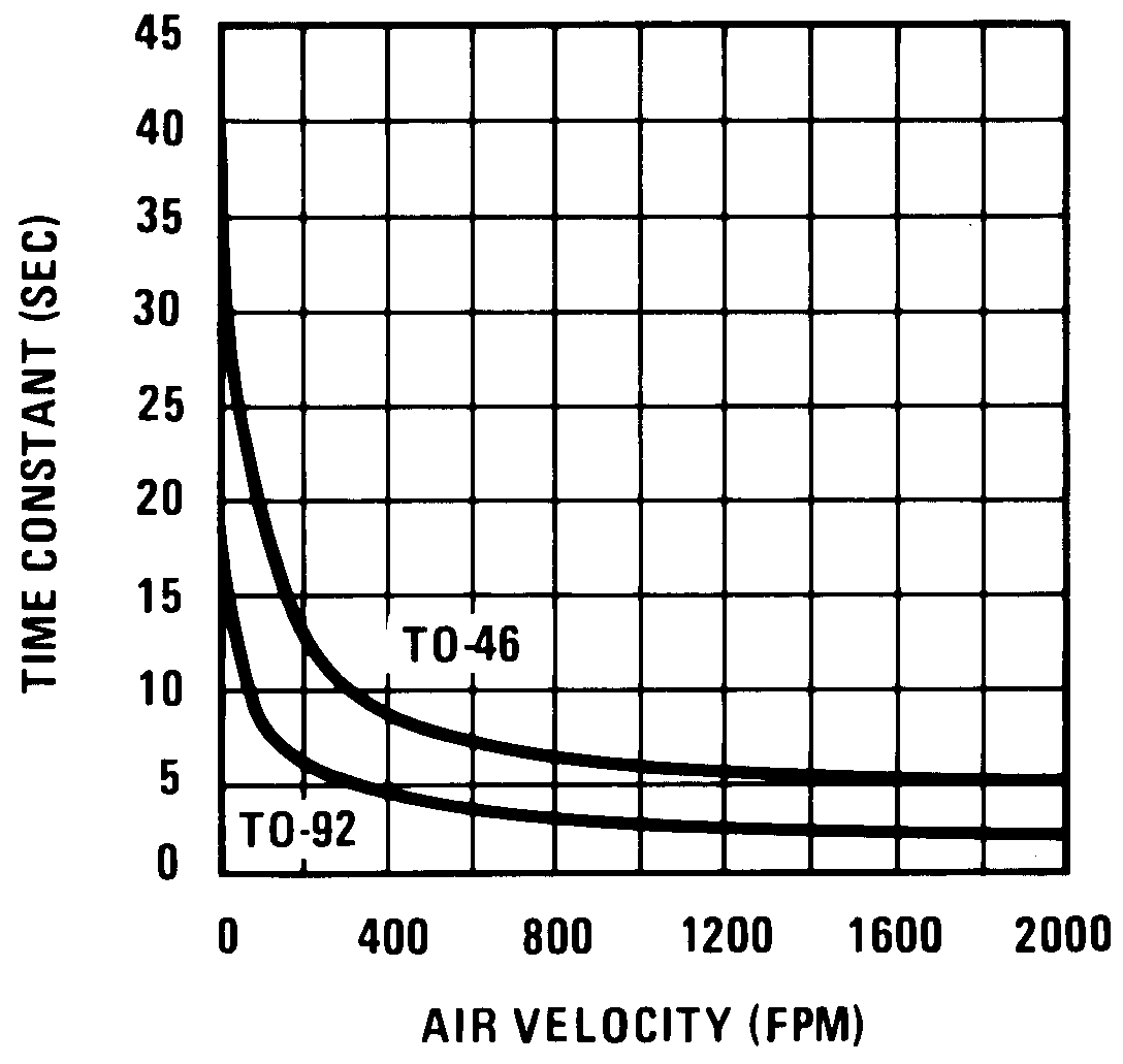 Figure 8. Thermal Time Constant
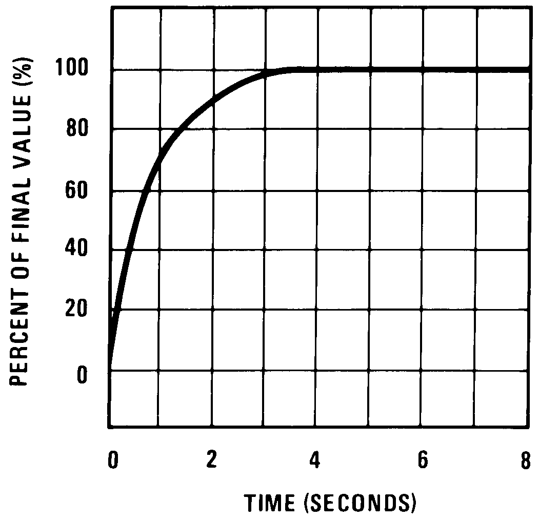 Figure 10. Thermal Response In Stirred Oil Bath