SNVS560E March 2008 – October 2017 LM2854
PRODUCTION DATA.
- 1 Features
- 2 Applications
- 3 Description
- 4 Revision History
- 5 Pin Configuration and Functions
- 6 Specifications
- 7 Detailed Description
-
8 Application and Implementation
- 8.1 Application Information
- 8.2
Typical Application
- 8.2.1 Design Requirements
- 8.2.2
Detailed Design Procedure
- 8.2.2.1 Input Filter Capacitor
- 8.2.2.2 AVIN Filtering Components
- 8.2.2.3 Soft-Start Capacitor
- 8.2.2.4 Tracking - Equal Soft-Start Time
- 8.2.2.5 Tracking - Equal Slew Rates
- 8.2.2.6 Enable and UVLO
- 8.2.2.7 Output Voltage Setting
- 8.2.2.8 Compensation Component Selection
- 8.2.2.9 Filter Inductor and Output Capacitor Selection
- 8.2.3 Application Curves
- 8.2.4 System Examples
- 9 Power Supply Recommendations
- 10Layout
- 11Device and Documentation Support
- 12Mechanical, Packaging, and Orderable Information
Package Options
Mechanical Data (Package|Pins)
- PWP|16
Thermal pad, mechanical data (Package|Pins)
- PWP|16
Orderable Information
7 Detailed Description
7.1 Overview
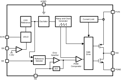
The LM2854 PowerWise synchronous DC-DC buck regulator belongs to the Texas Instruments family of switching regulators. Integration of the power MOSFETs and associated drivers, compensation component network, and the PWM controller reduces the number of external components necessary for a complete power supply design, without sacrificing performance.
7.2 Functional Block Diagram

7.3 Feature Description
7.3.1 Switching Frequency
The LM2854 is available in two switching frequency options, 500 kHz and 1 MHz. Generally, a higher switching frequency allows for faster transient response and a reduction in the footprint area and volume of the external power stage components, while a lower switching frequency affords better efficiency. These factors should be considered when selecting the appropriate switching frequency for a given application.
7.3.2 Enable
The LM2854 features a enable (EN) pin and associated comparator to allow the user to easily sequence the LM2854 from an external voltage rail, or to manually set the input UVLO threshold. The turnon or rising threshold and hysteresis for this comparator are typically 1.23 V and 0.15 V, respectively. The precise reference for the enable comparator allows the user to ensure that the LM2854 will be disabled when the system demands it to be.
7.3.3 Soft-Start
The LM2854 begins to operate when both the AVIN and EN voltages exceed the rising UVLO and enable thresholds, respectively. A controlled soft-start eliminates inrush currents during start-up and allows the user more control and flexibility when sequencing the LM2854 with other power supplies. An external soft-start capacitor is used to control the LM2854 start-up time. During soft-start, the voltage on the feedback pin is connected internally to the non-inverting input of the error amplifier. The soft-start period lasts until the voltage on the soft-start pin exceeds the LM2854 reference voltage of 0.8 V. At this point, the reference voltage takes over at the non-inverting amplifier input.
In the event of either AVIN or EN decreasing below the falling UVLO or enable threshold respectively, the voltage on the soft-start pin is collapsed by discharging the soft-start capacitor through a 5-kΩ transistor to ground.
7.3.4 Tracking
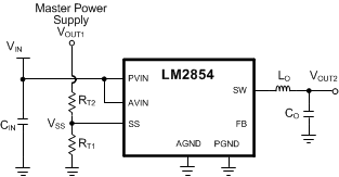
The LM2854 can track the output of a master power supply during soft-start by connecting a resistor divider to the SS pin. In this way, the output voltage slew rate of the LM2854 will be controlled by a master supply for loads that require precise sequencing. When the tracking function is used, a small value soft-start capacitor can be connected to the SS pin to alleviate output voltage overshoot when recovering from a current limit fault.
 Figure 14. Simplified Schematic Showing Use of Tracking
7.3.5 Pre-Biased Start-up Capability
The LM2854 is in a pre-biased state when the device starts up with an output voltage greater than zero. This often occurs in many multi-rail applications such as when powering an FPGA, ASIC, or DSP. The output can be pre-biased in these applications through parasitic conduction paths from one supply rail to another. Even though the LM2854 is a synchronous converter, it will not pull the output low when a pre-bias condition exists. The LM2854 will not sink current during start up until the soft-start voltage exceeds the voltage on the FB pin. Since the device can not sink current it protects the load from damage that might otherwise occur if current is conducted through the parasitic paths of the load.
7.3.6 Feedback Voltage Accuracy
The FB pin is connected to the inverting input of the voltage loop error amplifier and during closed loop operation its reference voltage is 0.8 V. The FB voltage is accurate to within –1.25% / +1% over temperature. Additionally, the LM2854 contains error nulling circuitry to substantially eliminate the feedback voltage over temperature drift as well as the long term aging effects of the internal amplifiers. In addition, the 1/f noise of the bandgap amplifier and reference are dramatically reduced. The manifestation of this circuit action is that the duty cycle will have two slightly different but distinct operating points, each evident every other switching cycle. The oscilloscope plot shown previously of the SW pin with infinite persistence set shows this behavior. No discernible effect is evident on the output due to LC filter attenuation. For further information, a Texas Instruments white paper is available on this topic.
7.3.7 Positive Current Limit
The LM2854 employs lossless cycle-by-cycle high-side current limit circuitry to limit the peak current through the high-side FET. The peak current limit threshold, denoted ICL, is nominally set at 6 A internally. When a current greater than ICL is sensed through the PFET, its on-time is immediately terminated and the NFET is activated. The NFET stays on for the entire next four switching cycles (effectively four PFET pulses are skipped). During these skipped pulses, the voltage on the soft-start pin is reduced by discharging the soft-start capacitor by a current sink on the soft-start pin of nominally 6 µA or 14 µA for the 500-kHz or 1-MHz options, respectively. Subsequent overcurrent events will drain more and more charge from the soft-start capacitor, effectively decreasing the reference voltage as the output droops due to the pulse skipping. Reactivation of the soft-start circuitry ensures that when the overcurrent situation is removed, the part will resume normal operation smoothly.
7.3.8 Negative Current Limit
The LM2854 implements negative current limit detection circuitry to prevent large negative current in the inductor. When the negative current sensed in the low-side NFET is below approximately –0.4 A, the present switching cycle is immediately terminated and both FETs are turned off. When both FETs are off, the negative inductor current originally flowing in the low-side NFET and into the SW pin commutates to the high-side PFET’s body diode and ramps back to zero. At this point, the SW pin becomes a high impedance node and ringing can be observed on the SW node as the stored energy in the inductor is dissipated while resonating with the parasitic nodal capacitance.
7.3.9 Overtemperature Protection
When the LM2854 senses a junction temperature greater than 165°C, both switching FETs are turned off and the part enters a sleep state. Upon sensing a junction temperature below 155°C, the part will re-initiate the soft-start sequence and begin switching once again. This feature is provided to prevent catastrophic failure due to excessive thermal dissipation.
7.3.10 Loop Compensation
The LM2854 preserves flexibility by integrating the control components around the error amplifier while using three small external compensation components from VOUT to FB. An integrated type II (two pole, one zero) voltage-mode compensation network is featured. To ensure stability, an external resistor and small value capacitor can be added across the upper feedback resistor as a pole-zero pair to complete a type III (three pole, two zero) compensation network. For correct selection of these components, see Detailed Design Procedure.
7.4 Device Functional Modes
7.4.1 Shutdown Mode
If EN is less than VIH – VEN(HSY), the LM2854 shuts down. Most internal circuitry is shut down, and the SW output is high-impedance. Once EN voltage exceeds VIH, the LM2854 enters soft-start mode.
7.4.2 Soft-Start and Track Mode
Once operation is initiated, the LM2854 starts charging its SS node. If a voltage is already present on the LM2854 circuit output, the LM2854 does not attempt to pull the circuit output low. If only a capacitor is connected to the SS pin, voltage on this pin rises, and once voltage exceeds 0.8 V, normal operating mode commences. If the high-side current limit is exceeded, the voltage on the SS pin is reduced, prolonging soft-start and track mode.
If a resistor divider is used to connect the SS pin to another power supply, Soft Start and Track mode can be used to cause the output of the LM2854 Buck to track this supply.
7.4.3 Normal Operating Mode
If the EN input of the LM2854 is above VIH and the SS pin is above 0.8 V, output is regulated normally. If EN is reduced to less than VIH – VEN(HSY), the LM2854 enters shutdown mode. If the high-side current limit is activated or SS is pulled to below 0.8 V, the LM2854 enters soft-start and track mode.