SNIS160E May 1999 – February 2015 LM135 , LM135A , LM235 , LM235A , LM335 , LM335A
PRODUCTION DATA.
- 1 Features
- 2 Applications
- 3 Description
- 4 Revision History
- 5 Pin Configuration and Functions
- 6 Specifications
- 7 Detailed Description
- 8 Application and Implementation
- 9 Power Supply Recommendations
- 10Layout
- 11Device and Documentation Support
- 12Mechanical, Packaging, and Orderable Information
Package Options
Mechanical Data (Package|Pins)
Thermal pad, mechanical data (Package|Pins)
Orderable Information
8 Application and Implementation
NOTE
Information in the following applications sections is not part of the TI component specification, and TI does not warrant its accuracy or completeness. TI’s customers are responsible for determining suitability of components for their purposes. Customers should validate and test their design implementation to confirm system functionality.
8.1 Application Information
To insure good sensing accuracy, several precautions must be taken. Like any temperature-sensing device, self-heating can reduce accuracy. The LM135 should be operated at the lowest current suitable for the application. Sufficient current, of course, must be available to drive both the sensor and the calibration pot at the maximum operating temperature as well as any external loads.
If the sensor is used in an ambient where the thermal resistance is constant, self-heating errors can be calibrated out. This is possible if the device is run with a temperature-stable current. Heating will then be proportional to zener voltage and therefore temperature. This makes the self-heating error proportional to absolute temperature the same as scale factor errors.
8.2 Typical Application
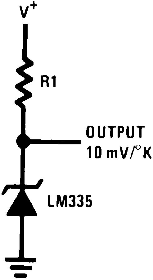 Figure 13. Basic Temperature Sensor
8.2.1 Design Requirements
Table 1. Design Parameters
| PARAMETER | EXAMPLE VALUE |
|---|---|
| Accuracy at 25°C | ±1°C |
| Accuracy from –55 °C to 150 °C | ±2.7°C |
| Forward Current | 1 mA |
| Temperature Slope | 10m V/K |
8.2.2 Detailed Design Procedure
For optimum accuracy, R1 is picked such that 1 mA flows through the sensor. Additional error can be introduced by varying load currents or varying supply voltage. The influence of these currents on the minimum and maximum reverse current flowing through the LM135 should be calculated and be maintained in the range of 0.4 mA to 5 mA. Minimizing the current variation through the LM135 will provide for the best accuracy. The Operating Output Voltage Change with Current specification can be used to calculate the additional error which could be up to 1 K maximum from the LM135A, for example.
8.2.3 Application Curve
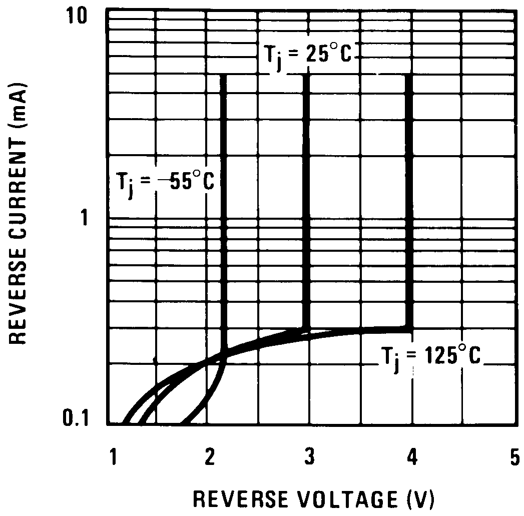 Figure 14. Reverse Characteristics
8.3 System Examples
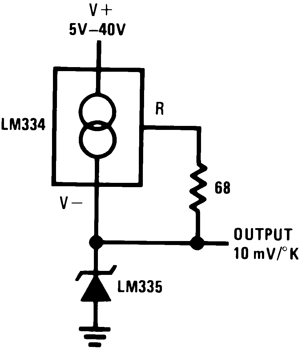 Figure 15. Wide Operating Supply
| Wire length for 1°C error due to wire drop |
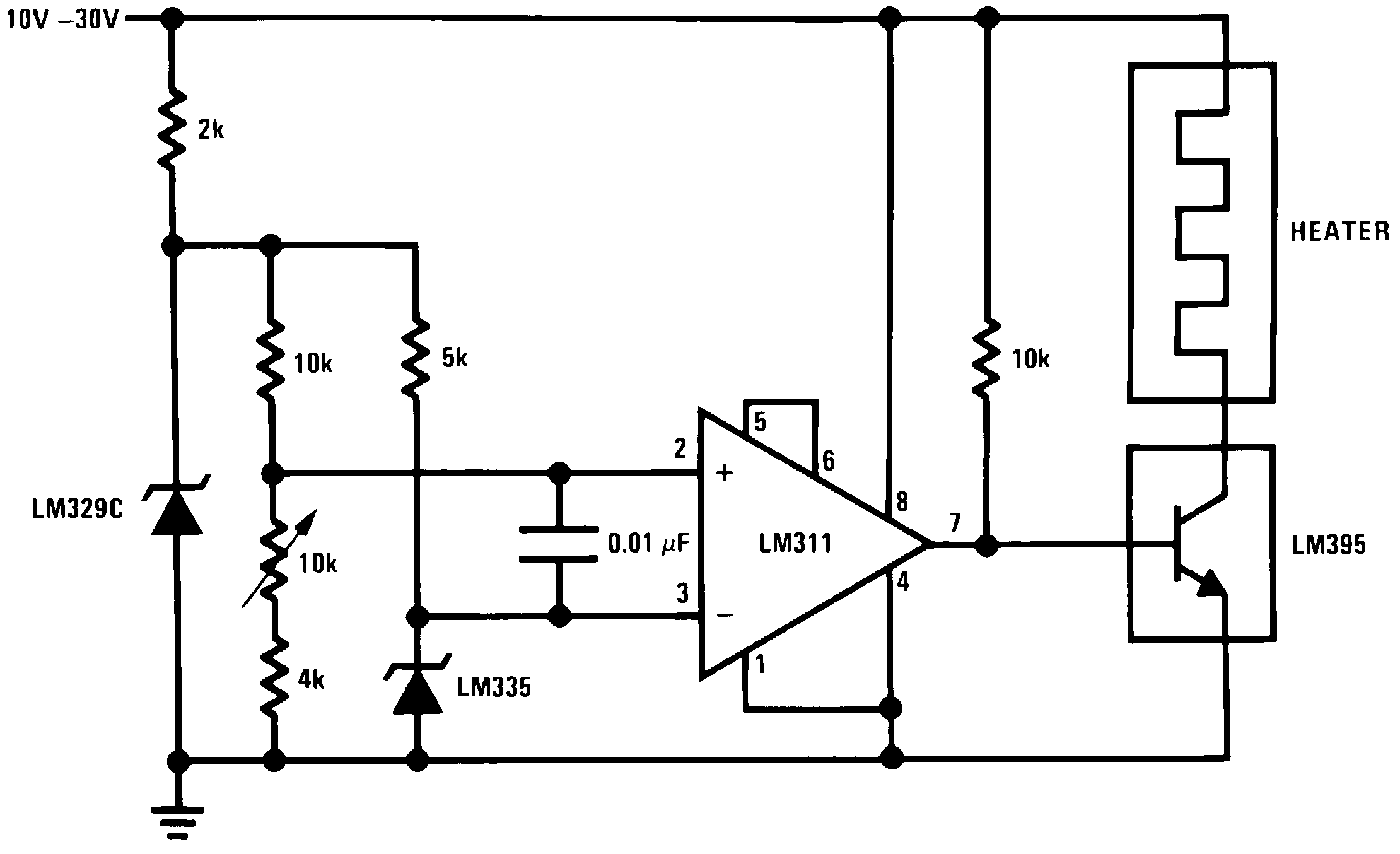 Figure 19. Simple Temperature Controller
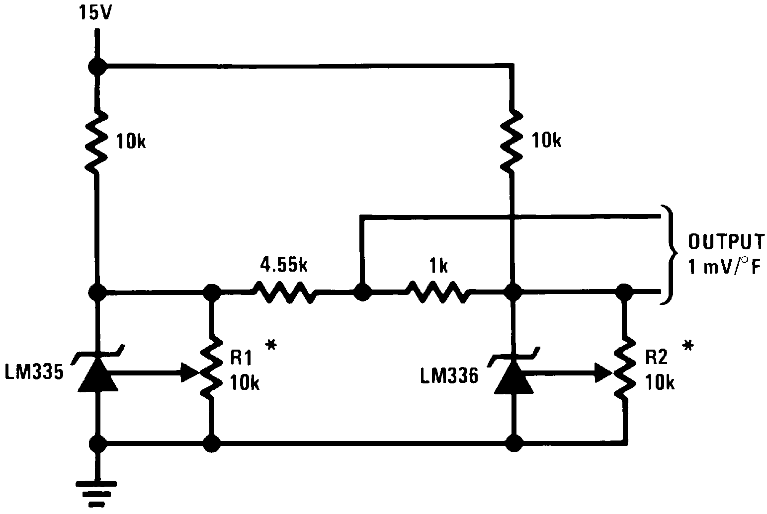
| Adjust R2 for 2.554V across LM336. | ||
| Adjust R1 for correct output. |
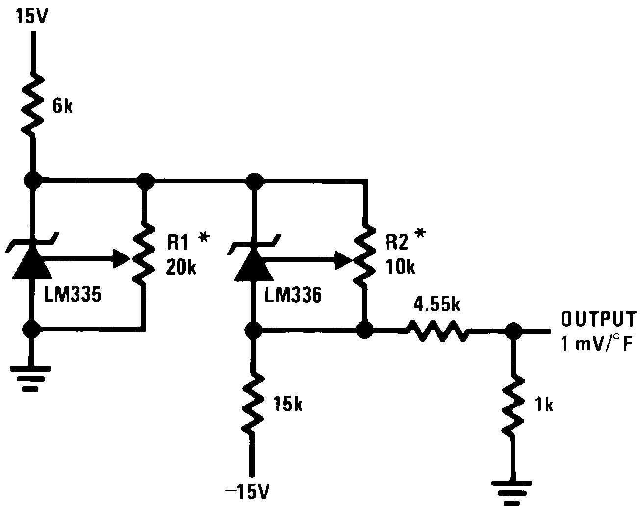
| To calibrate adjust R2 for 2.554V across LM336. | ||
| Adjust R1 for correct output. | ||
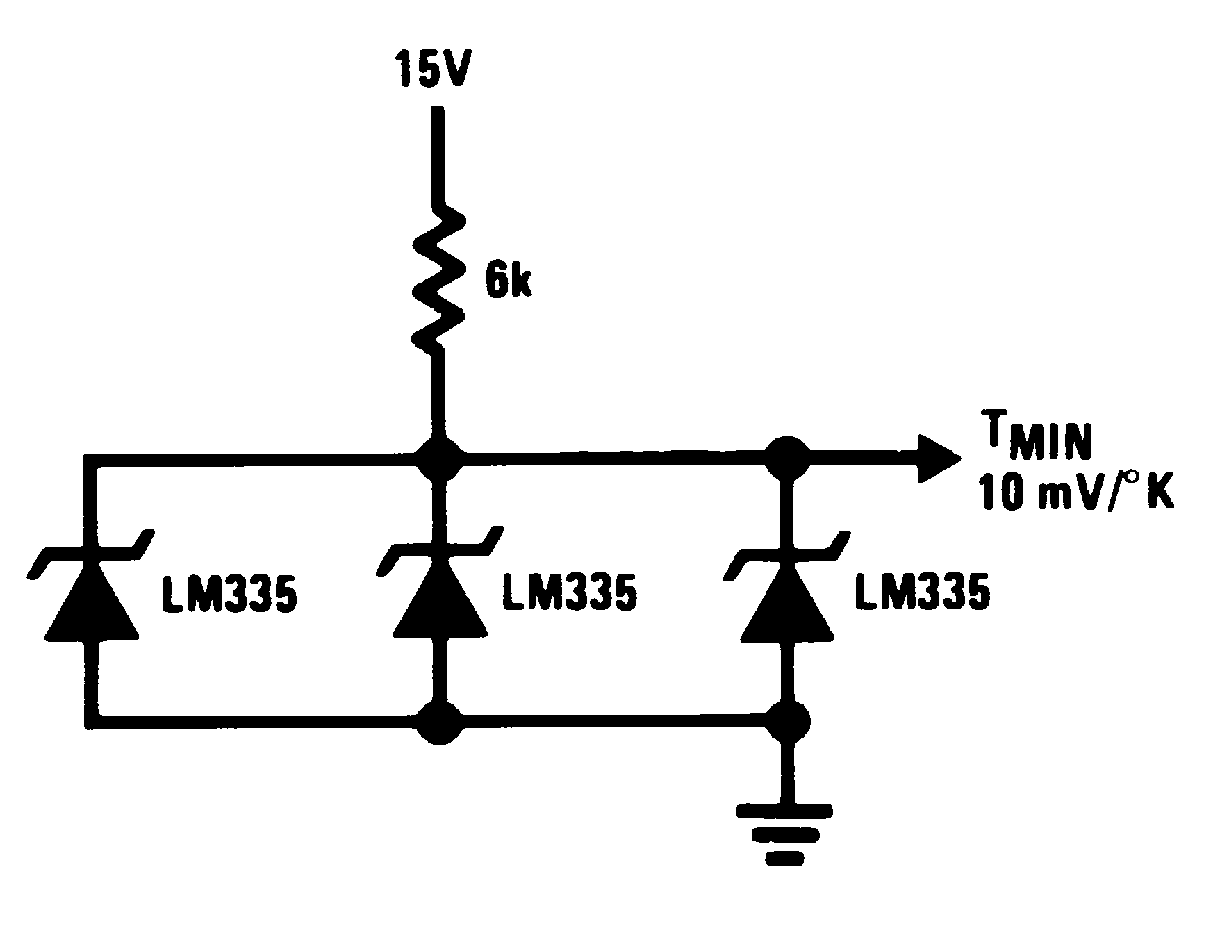 Figure 16. Minimum Temperature Sensing
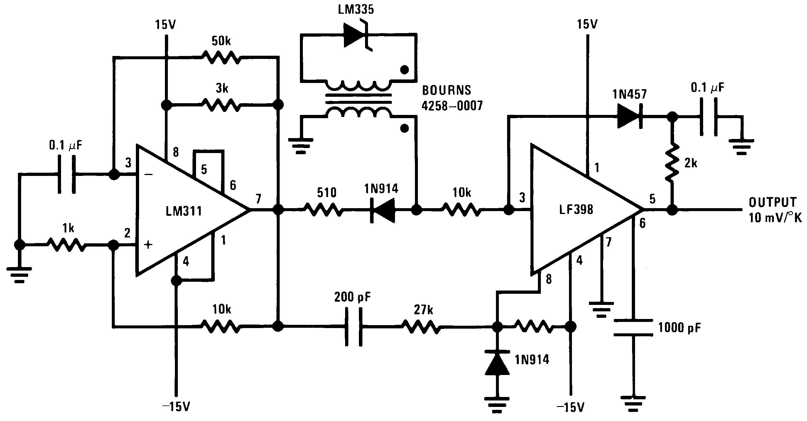 Figure 18. Isolated Temperature Sensor
 Figure 20. Simple Temperature Control
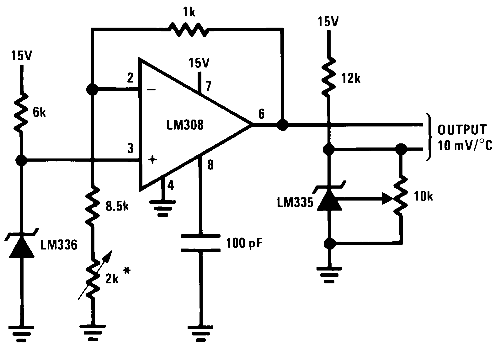
| Adjust for 2.7315V at output of LM308 |
8.3.1 Thermocouple Cold Junction Compensation
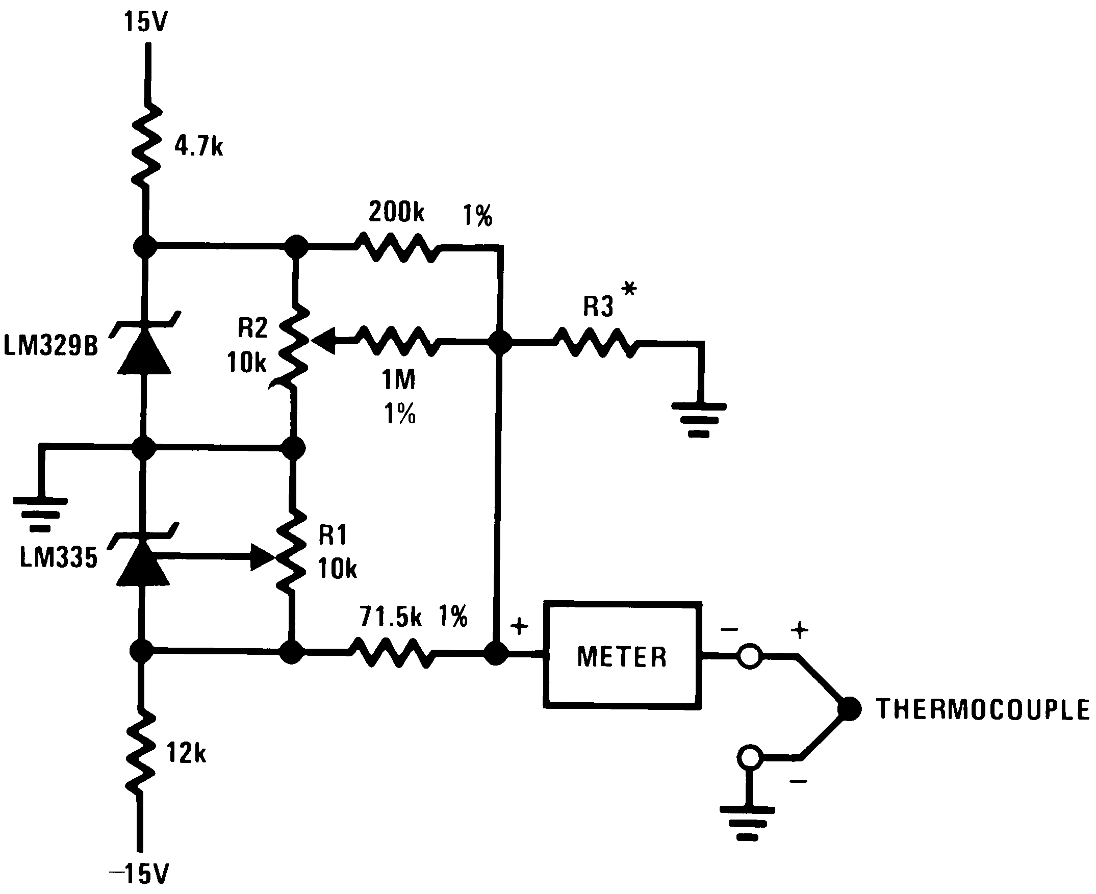
| THERMO-COUPLE | R3 (±1%) | SEEBECK COEFFICIENT |
|---|---|---|
| J | 377 Ω | 52.3 μV/°C |
| T | 308 Ω | 42.8 μV/°C |
| K | 293 Ω | 40.8 μV/°C |
| S | 45.8 Ω | 6.4 μV/°C |
Adjustments: Compensates for both sensor and resistor tolerances
J 14.32 mV K 11.17 mV T 11.79 mV S 1.768 mV |
||
| THERMO-COUPLE | R3 | R4 | SEEBECK COEFFICIENT |
|---|---|---|---|
| J | 1.05K | 385Ω | 52.3 μV/°C |
| T | 856Ω | 315Ω | 42.8 μV/°C |
| K | 816Ω | 300Ω | 40.8 μV/°C |
| S | 128Ω | 46.3Ω | 6.4 μV/°C |
Adjustments:
|
|||
| J | 14.32 mV | ||
| T | 11.79 mV | ||
| K | 11.17 mV | ||
| S | 1.768 mV | ||
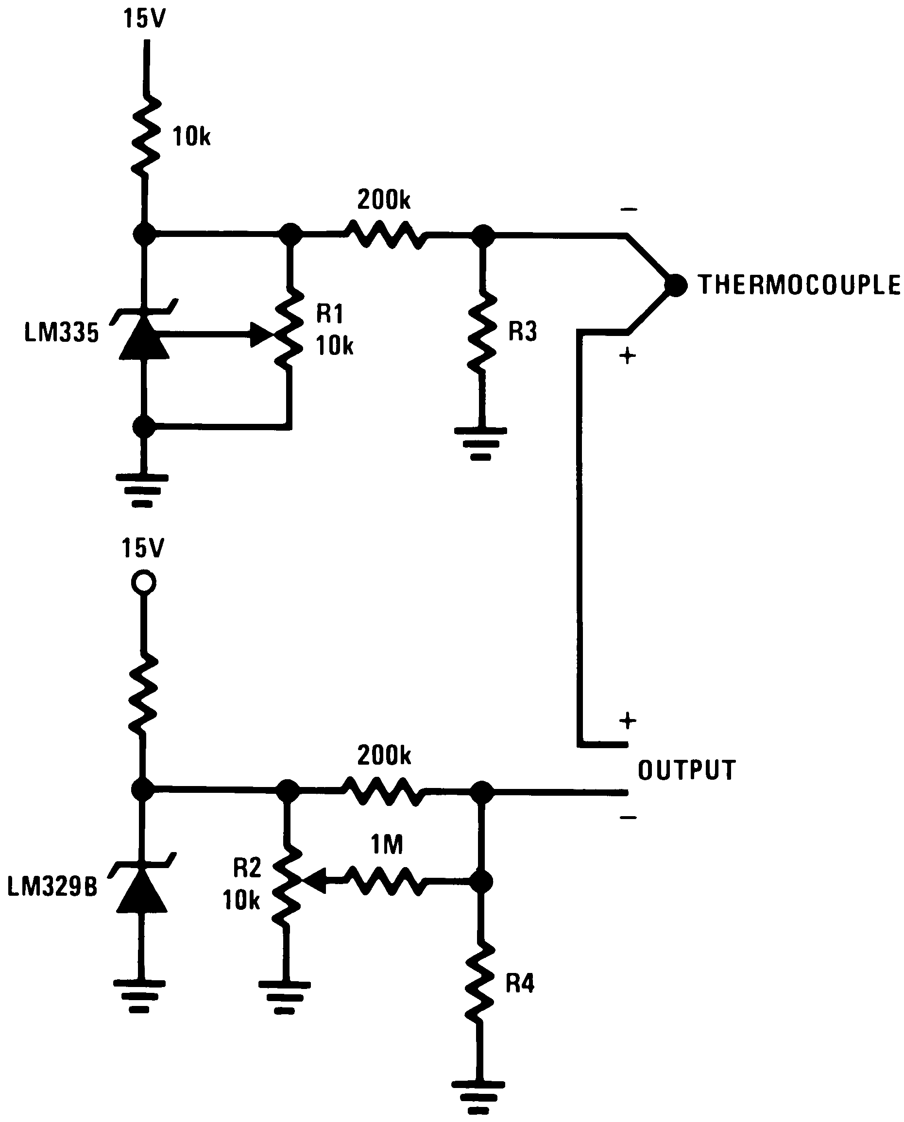
| Select R3 and R4 for thermocouple type |
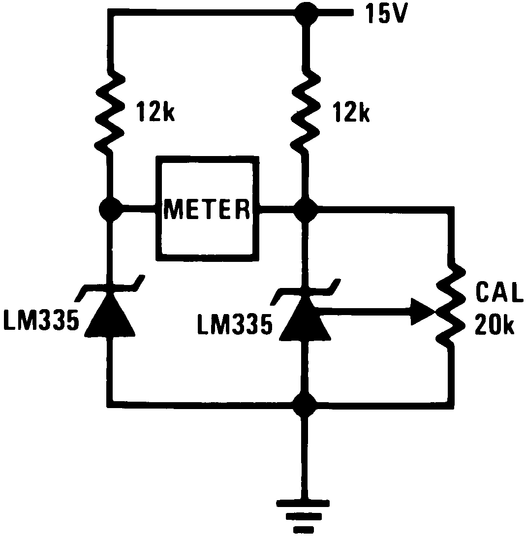 Figure 27. Differential Temperature Sensor
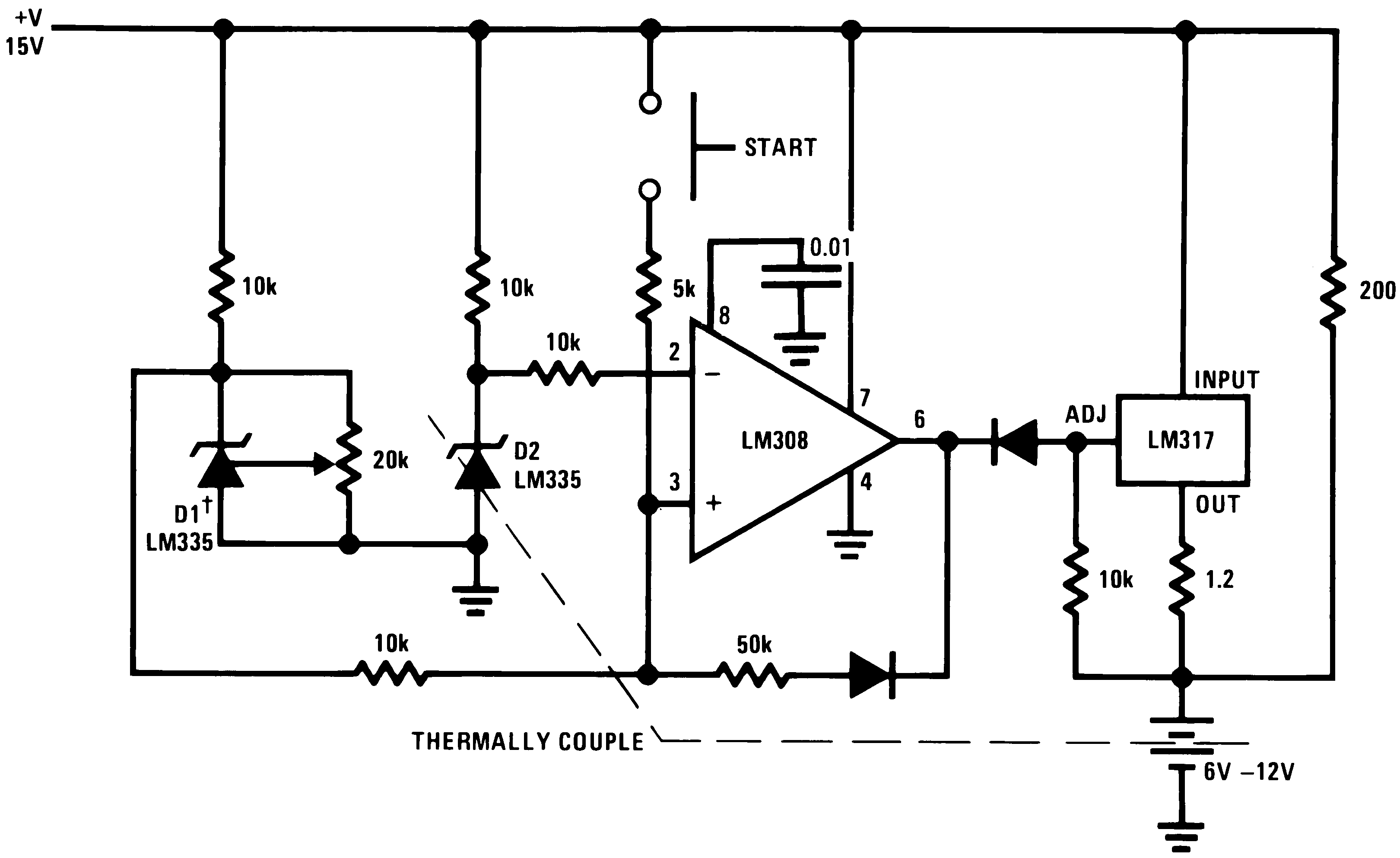
| Adjust D1 to 50 mV greater VZ than D2. | ||
| Charge terminates on 5°C temperature rise. | ||
| Couple D2 to battery. |
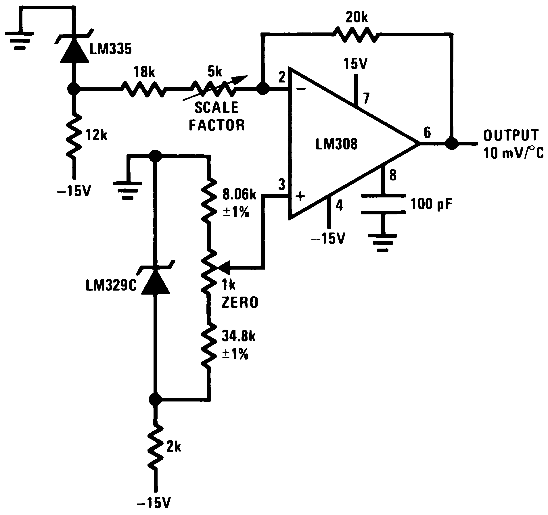 Figure 31. Ground Referred Centigrade Thermometer
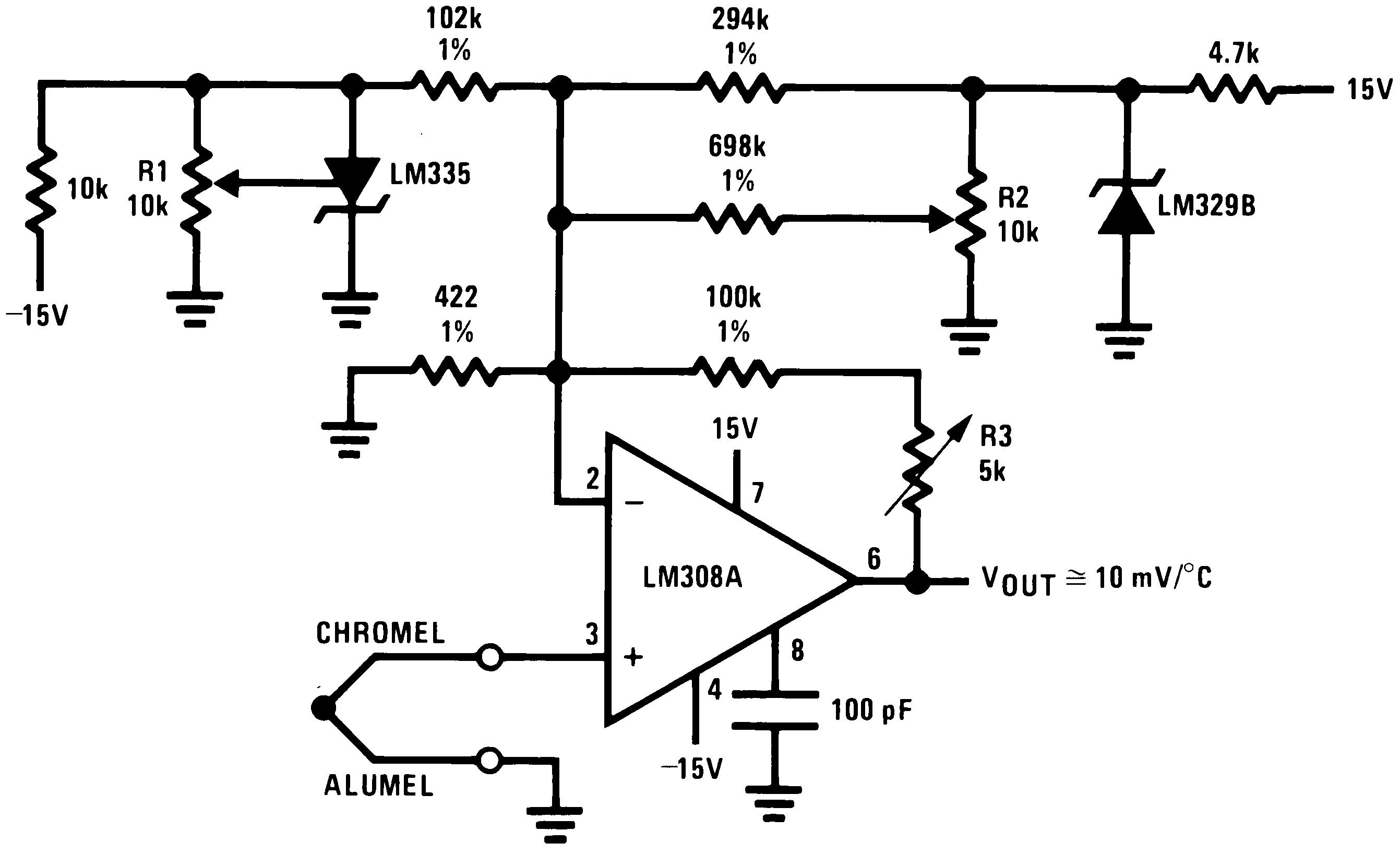
| Terminate thermocouple reference junction in close proximity to LM335. | ||
| Adjustments: | ||
| 1. Apply signal in place of thermocouple and adjust R3 for a gain of 245.7. | ||
| 2. Short non-inverting input of LM308A and output of LM329B to ground. | ||
| 3. Adjust R1 so that VOUT = 2.982V @ 25°C. | ||
| 4. Remove short across LM329B and adjust R2 so that VOUT = 246 mV @ 25°C. | ||
| 5. Remove short across thermocouple. |
Figure 28. Differential Temperature Sensor
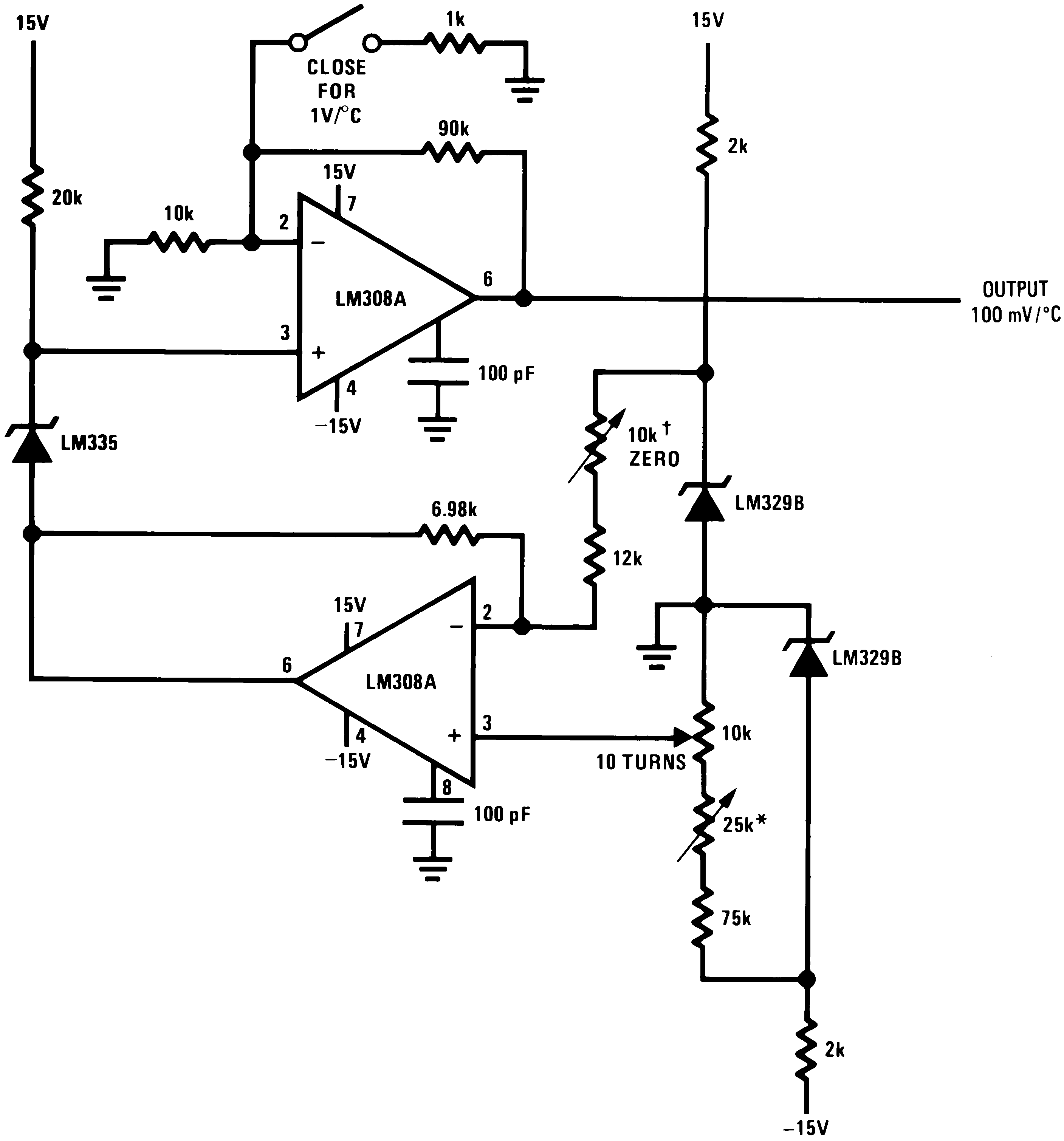
| Adjust for zero with sensor at 0°C and 10T pot set at 0°C | ||
| Adjust for zero output with 10T pot set at 100°C and sensor at 100°C | ||
| Output reads difference between temperature and dial setting of 10T pot |
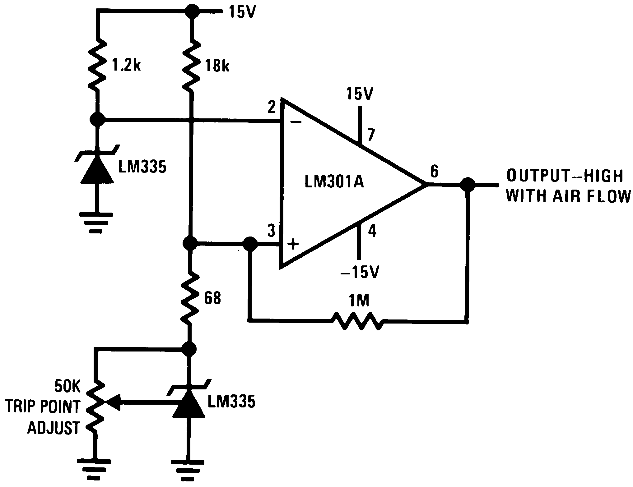
| *Self heating is used to detect air flow |