SNVS606L June 2009 – December 2014 LM3530
PRODUCTION DATA.
- 1 Features
- 2 Applications
- 3 Description
- 4 Revision History
- 5 I2C Device Options
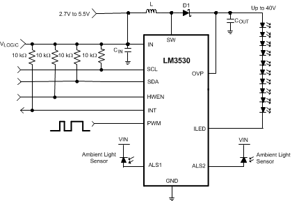
- 6 Pin Configuration and Functions
- 7 Specifications
-
8 Detailed Description
- 8.1 Overview
- 8.2 Functional Block Diagram
- 8.3
Feature Description
- 8.3.1 Start-Up
- 8.3.2 Light Load Operation
- 8.3.3 Ambient Light Sensor
- 8.3.4 ALS Operation
- 8.3.5 ALS Averaging Time
- 8.3.6 Zone Boundary Settings
- 8.3.7 Zone Boundary Trip Points and Hysteresis
- 8.3.8 Minimum Zone Boundary Settings
- 8.3.9 LED Current Control
- 8.3.10 Exponential or Linear Brightness Mapping Modes
- 8.3.11 PWM Input Polarity
- 8.3.12 I2C-Compatible Current Control Only
- 8.3.13 Simple Enable Disable With PWM Current Control
- 8.3.14 Ambient Light Current Control
- 8.3.15 Ambient Light Current Control + PWM
- 8.3.16 Interrupt Output
- 8.3.17 Overvoltage Protection
- 8.3.18 Hardware Enable
- 8.3.19 Thermal Shutdown
- 8.4 Device Functional Modes
- 8.5 Programming
- 8.6 Register Maps
- 9 Application and Implementation
- 10Power Supply Recommendations
- 11Layout
- 12Device and Documentation Support
- 13Mechanical, Packaging, and Orderable Information
Package Options
Mechanical Data (Package|Pins)
Thermal pad, mechanical data (Package|Pins)
Orderable Information
1 Features
- Drives up to 11 LEDs in series
- 1000:1 Dimming Ratio
- 90% Efficient
- Programmable Dual Ambient Light Sensor Inputs with Internal ALS Voltage Setting Resistors
- I2C Programmable Logarithmic or Linear Brightness Control
- External PWM Input for Simple Brightness Adjustment
- True Shutdown Isolation for LEDs and Ambient Light Sensors
- Internal Soft-Start Limits Inrush Current
- Wide 2.7-V to 5.5-V Input Voltage Range
- 40-V and 25-V Overvoltage Protection Options
- 500-kHz Fixed Frequency Operation
- 839-mA Peak Current Limit
2 Applications
- Smartphone LCD Backlighting
- Personal Navigation LCD Backlighting
- 2 to 11 Series White-LED Backlit Display Power Source
3 Description
The LM3530 current mode boost converter supplies the power and controls the current in up to 11 series white LEDs. The 839-mA current limit and 2.7-V to 5.5-V input voltage range make the device a versatile backlight power source ideal for operation in portable applications.
The LED current is adjustable from 0 mA to 29.5 mA via an I2C-compatible interface. The 127 different current steps and 8 different maximum LED current levels give over 1000 programmable LED current levels. Additionally, PWM brightness control is possible through an external logic level input.
The device also features two Ambient Light Sensor inputs. These are designed to monitor analog output ambient light sensors and provide programmable adjustment of the LED current with changes in ambient light. Each ambient light sensor input has independently programmable internal voltage setting resistors which can be made high impedance to reduce power during shutdown. The 500-kHz switching frequency allows for high converter efficiency over a wide output voltage range accommodating from 2 to 11 series LEDs. Finally, the support of Content Adjusted Backlighting maximizes battery life while maintaining display image quality.
The LM3530 operates over the −40°C to 85°C temperature range.
Device Information(1)
| PART NUMBER | PACKAGE | BODY SIZE (MAX) |
|---|---|---|
| LM3530 | DSBGA (12) | 1.64 mm x 1.24 mm |
- For all available packages, see the orderable addendum at the end of the datasheet.
Simplified Schematic