SNOS745D May 1998 – November 2023 LM6171
PRODUCTION DATA
- 1
- 1 Features
- 2 Applications
- 3 Description
- 4 Pin Configuration and Functions
- 5 Specifications
- 6 Detailed Description
- 7 Application and Implementation
- 8 Device and Documentation Support
- 9 Revision History
- 10Mechanical, Packaging, and Orderable Information
Package Options
Refer to the PDF data sheet for device specific package drawings
Mechanical Data (Package|Pins)
- D|8
- P|8
Thermal pad, mechanical data (Package|Pins)
Orderable Information
7.1.4 Driving Capacitive Loads
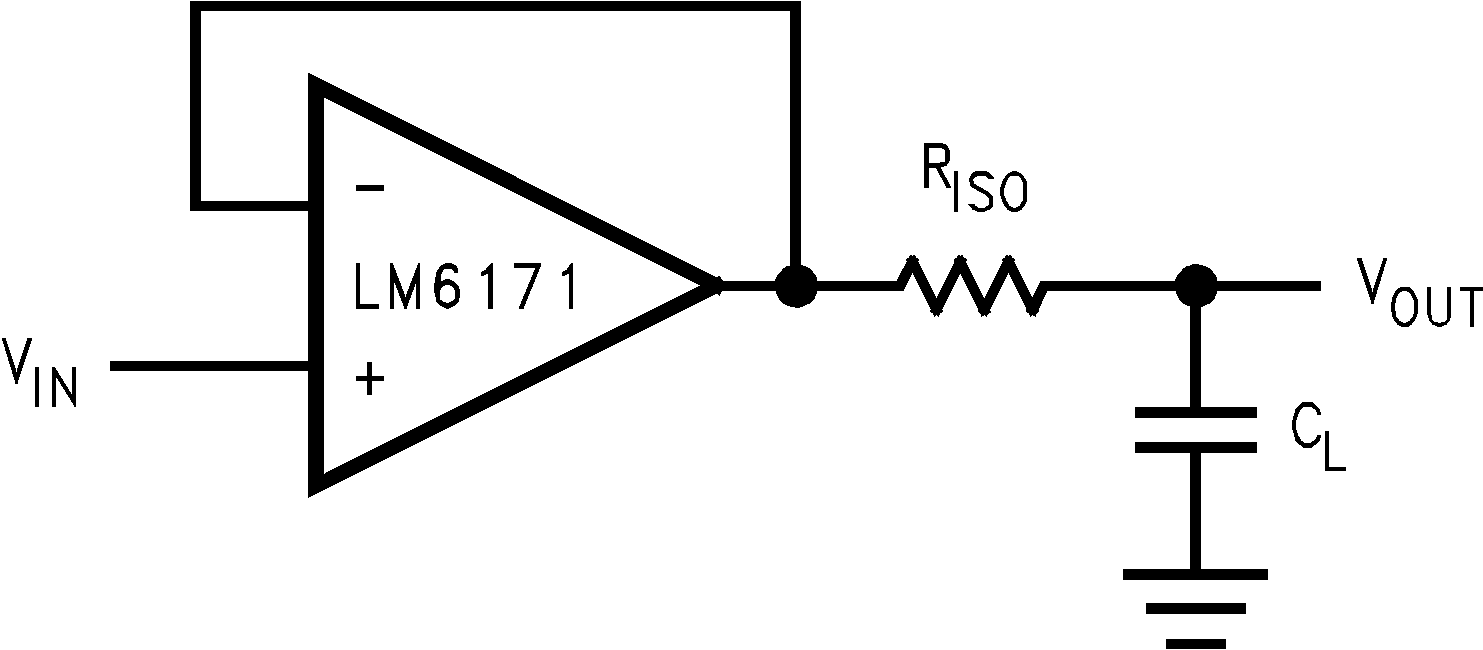
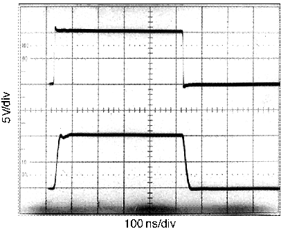
Amplifiers driving capacitive loads can oscillate or have ringing at the output. To eliminate oscillation or reduce ringing, place an isolation resistor as shown in Figure 7-5. The combination of the isolation resistor and the load capacitor forms a pole to increase stability by adding more phase margin to the overall system. The desired performance depends on the value of the isolation resistor; the bigger the isolation resistor, the more damped the pulse response becomes. For the LM6171, a 50‑Ω isolation resistor is recommended for initial evaluation. Figure 7-6 shows the LM6171 driving a 200‑pF load with the 50‑Ω isolation resistor.
 Figure 7-5 Isolation Resistor Used to
Drive Capacitive Load
 Figure 7-6 The LM6171 Driving a 200‑pF
Load With a 50‑Ω Isolation Resistor