SLVSFD0 September 2019 LM74202-Q1
PRODUCTION DATA.
- 1 Features
- 2 Applications
- 3 Description
- 4 Revision History
- 5 Pin Configuration and Functions
- 6 Specifications
- 7 Parameter Measurement Information
-
8 Detailed Description
- 8.1 Overview
- 8.2 Functional Block Diagram
- 8.3
Feature Description
- 8.3.1 Undervoltage Lockout (UVLO)
- 8.3.2 Overvoltage Protection (OVP)
- 8.3.3 Reverse Battery Protection
- 8.3.4 Hot Plug-In and In-Rush Current Control
- 8.3.5 Overload and Short Circuit Protection
- 8.4 Device Functional Modes
-
9 Application and Implementation
- 9.1 Application Information
- 9.2
Typical Application
- 9.2.1 Design Requirements
- 9.2.2 Detailed Design Procedure
- 9.2.3 Application Curves
- 10Power Supply Recommendations
- 11Layout
- 12Device and Documentation Support
- 13Mechanical, Packaging, and Orderable Information
Package Options
Mechanical Data (Package|Pins)
- PWP|16
Thermal pad, mechanical data (Package|Pins)
- PWP|16
Orderable Information
8.3.5.1.1 Active Current Limiting
When the active current limiting mode is selected, during overload events, the device continuously regulates the load current to the overcurrent limit I(OL) programmed by the R(ILIM) resistor as shown in Equation 4.

where
- I(OL) is the overload current limit in Ampere
- R(ILIM) is the current limit resistor in kΩ
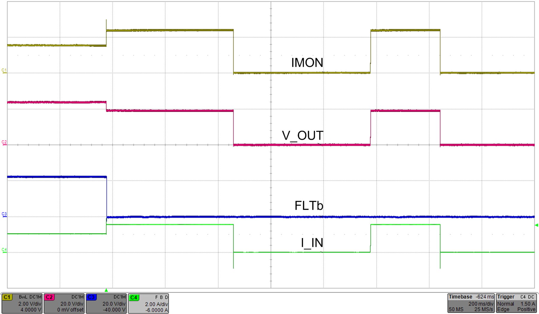
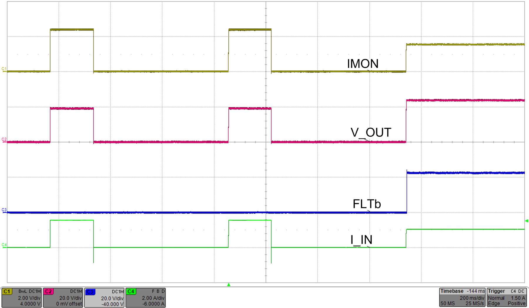
During an overload condition, the internal current-limit amplifier regulates the output current to I(LIM). The FLT signal assert after a delay of tPGOODF. The output voltage droops during the current regulation, resulting in increased power dissipation in the device. If the device junction temperature reaches the thermal shutdown threshold (T(TSD)), the internal FET is turn off. The device configured in latch-off mode stays latched off until it is reset by either of the following conditions:
- Cycling V(IN) below V(PORF)
- Toggling SHDN
When the device is configured in auto-retry mode, it commences an auto-retry cycle tCBretry(dly) ms after TJ < [T(TSD) – 10°C]. The FLT signal remains asserted until the fault condition is removed and the device resumes normal operation. Figure 29 and Figure 30 illustrates the behavior of the system during current limiting with auto-retry functionality.

| Load transition from 22 Ω to 12 Ω | MODE pin connected to RTN | |
| RILIM = 8 kΩ | ||

| RILIM = 5.36 kΩ | ||