SLLSE41H June 2010 – March 2016 SN75LVCP601
PRODUCTION DATA.
- 1 Features
- 2 Applications
- 3 Description
- 4 Revision History
- 5 Pin Configuration and Functions
- 6 Specifications
- 7 Parameter Measurement Information
- 8 Detailed Description
- 9 Application and Implementation
- 10Power Supply Recommendations
- 11Layout
- 12Device and Documentation Support
- 13Mechanical, Packaging, and Orderable Information
Package Options
Mechanical Data (Package|Pins)
- RTJ|20
Thermal pad, mechanical data (Package|Pins)
- RTJ|20
Orderable Information
9 Application and Implementation
NOTE
Information in the following applications sections is not part of the TI component specification, and TI does not warrant its accuracy or completeness. TI’s customers are responsible for determining suitability of components for their purposes. Customers should validate and test their design implementation to confirm system functionality.
9.1 Application Information
The SN75LVCP601 is a dual-channel SATA redriver and signal conditioner supporting data rates of 6 Gbps. The inputs incorporate an OOB (out-of-band) detector, which automatically squelches the output while maintaining a stable common-mode voltage compliant to the SATA link.
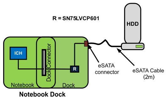 Figure 26. Typical SN75LVCP601 Placement in the System
9.2 Typical Application
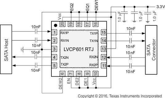
This typical application describes how to configure the EQ, DE, and DEW configuration pins of the SN75LVCP601 device based on board trace length between the SATA Host and the SN75LVCP601 and the SN75LVCP601 and SATA Device. Actual configuration settings may differ due to additional factors such as board layout, trace widths, and connectors used in the signal path.
9.2.1 Design Requirements
Typically, system trace length from the SATA host to the SN75LVCP601 device and trace length from the SN75LVCP601 device to a SATA device differ and require different equalization and de-emphasis settings for the host side and device side.
For example:
- A system with a 6-inch trace from the SN75LVCP601 device to a SATA host may set EQ1 (Rx1±) to 7 dB, and DE2 (Tx2±) to –2 dB and DEW2 (Tx2±) to long pulse duration.
- The same system with a 1-inch trace from the SN75LVCP601 device to a SATA HDD may set EQ2 (Rx2±) to 0 dB, and DE1 (Tx1±) to 0 dB and DEW1 (Tx1±) to short pulse duration.
Refer to Application Curves for recommended EQ, DE and DEW settings based on trace length. It is highly recommended to add both pullup- and pulldown-resistor options in the layout to fine-tune the settings if needed.
Input Signal Characteristics:
- Data Rate: 6 Gbps
- Pattern: PRBS7
- No pre-emphasis
- Signal amplitude: 500 mVp-p
- 18-inch SMA cable from test equipment to input and output trace
 Figure 28. Measurement Set-up
9.2.2 Detailed Design Procedure
9.2.2.1 Equalization Configuration
Each differential input of the SN75LVCP601 device has programmable equalization in the front stage. The equalization setting is shown in Table 2. The input equalizer is designed to recover a signal even when no eye is present at the receiver and effectively supports FR4 trace input from 3 inches to greater than 24 inches at
SATA 6 Gbps speed.
Table 2. Equalization Settings
| EQ1, EQ2 | CH1, CH2 EQUALIZATION dB (AT 6 Gbps) |
|---|---|
| NC | 0 |
| 0 | 7 |
| 1 | 14 |
9.2.2.2 De-emphasis Configuration
The SN75LVCP601 device provides the de-emphasis settings shown in Table 3. De-emphasis is controlled independently for each channel and is set by the DE1, DE2, DEW1 and DEW2 pins of the SN75LVCP601 device. The recommended settings for these pins are listed in Application Curves. Output de-emphasis is capable of supporting FR4 trace lengths at the output from 3 inches to 12+ inches at SATA 6 Gbps speed.
Table 3. De-emphasis Settings
| DE1, DE2 | CH1, CH2 DE-EMPHASIS dB (AT 6 Gbps) |
|---|---|
| 0 | 0 |
| 1 | –2 |
| NC | –4 |
Table 4. DE Width Control
| DEW1, DEW2 | DE-EMPHASIS WIDTH FOR CH1, CH2 |
|---|---|
| 0 | Short de-emphasis pulse duration |
| 1 | Long de-emphasis pulse duration |
9.2.3 Application Curves
9.2.3.1 SN75LVCP601 Equalization Settings For Various Input Trace Lengths
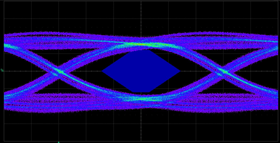
EQ1, EQ2 Setting = NC (0 dB)
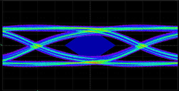
EQ1, EQ2 Setting = 0 (7 dB)
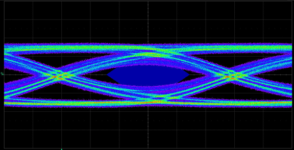
EQ1, EQ2 Setting = 0 (7 dB)
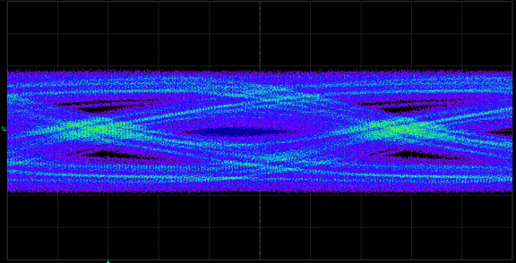
EQ1, EQ2 Setting = 0 (7 dB)
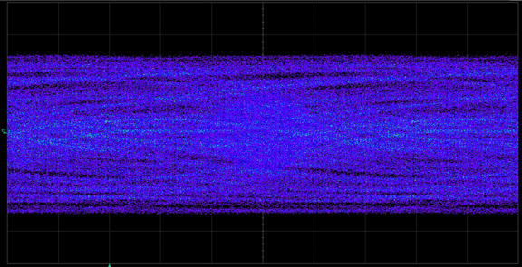
EQ1, EQ2 Setting = 1 (14 dB)
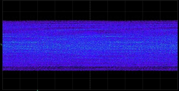
EQ1, EQ2 Setting = 1 (14 dB)
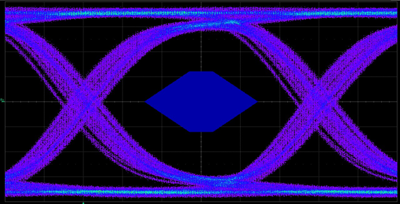
EQ1, EQ2 Setting = NC (0 dB)
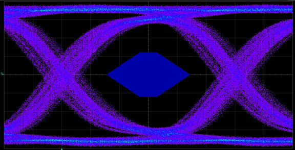
EQ1, EQ2 Setting = 0 (7 dB)
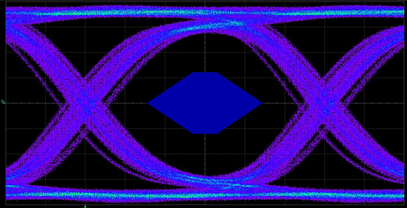
EQ1, EQ2 Setting = 0 (7 dB)
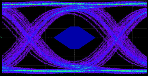
EQ1, EQ2 Setting = 0 (7 dB)
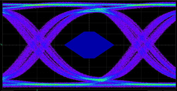
EQ1, EQ2 Setting = 1 (14 dB)
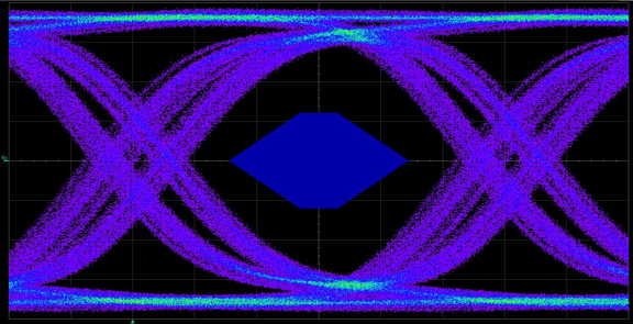
EQ1, EQ2 Setting = 1 (14 dB)
9.2.3.2 SN75LVCP601 De-emphasis Settings For Various Output Trace Lengths
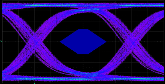
DE1, DE2 Setting = 0 (0 dB)
DEW1, DEW2 Setting = 0 (Short pulse duration)
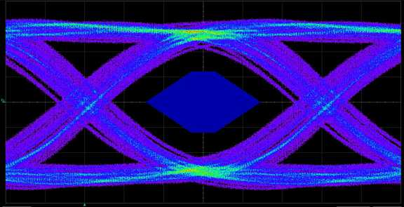
DE1, DE2 Setting = 1 (–2 dB)
DEW1, DEW2 Setting = 1 (Long pulse duration)
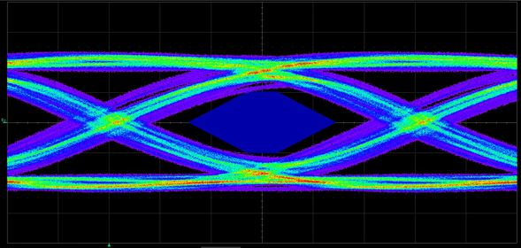
| Output Trace Length = 12 in. | |||
| DE1, DE2 Setting = NC (–4 dB | |||
| DEW1, DEW2 Setting = 1 (Long pulse duration) | |||
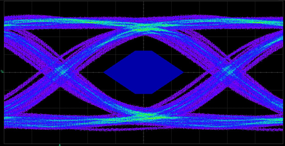
DE1, DE2 Setting = 0 (0 dB)
DEW1, DEW2 Setting = 0 (Short pulse duration)
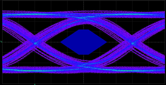
DE1, DE2 Setting = 1 (–2 dB)
DEW1, DEW2 Setting = 1 (Long pulse duration)