SLVSEJ1A February 2021 – May 2022 TLC6983
PRODUCTION DATA
- 1 Features
- 2 Applications
- 3 Description
- 4 Revision History
- 5 Description (continued)
- 6 Pin Configuration and Functions
- 7 Specifications
-
8 Detailed Description
- 8.1 Overview
- 8.2 Functional Block Diagram
- 8.3
Feature Description
- 8.3.1 Independent and Stackable Mode
- 8.3.2 Current Setting
- 8.3.3 Frequency Multiplier
- 8.3.4 Line Transitioning Sequence
- 8.3.5 Protections and Diagnostics
- 8.4 Device Functional Modes
- 8.5 Continuous Clock Series Interface
- 8.6 PWM Grayscale Control
- 8.7 Register Maps
- 9 Application and Implementation
- 10Power Supply Recommendations
- 11Layout
- 12Device and Documentation Support
- 13Mechanical, Packaging, and Orderable Information
Package Options
Mechanical Data (Package|Pins)
Thermal pad, mechanical data (Package|Pins)
Orderable Information
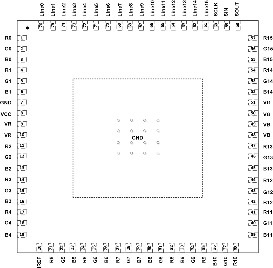
6 Pin Configuration and Functions
 Figure 6-1 TLC6983 RRF
Package
76-Pin VQFN with Exposed Thermal Pad
Top View
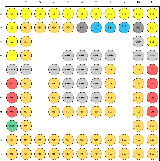
 Figure 6-2 TLC6983 ZXL Package
96-Pin BGA
Top View
Figure 6-2 TLC6983 ZXL Package
96-Pin BGA
Top ViewTable 6-1 Pin Functions
| PIN | I/O | DESCRIPTION | ||
|---|---|---|---|---|
| NAME | RRF NO. | ZXL NO. | ||
| IREF | 20 | J1 | I | Pin for setting the maximum constant-current value. Connecting an external resistor between IREF and GND sets the maximum current for each constant-current output channel. When this pin is connected directly to GND, all outputs are forced off. The external resistor must be placed close to the device. |
| VCC | 8 | F1 | I | Device power supply |
| VR | 9, 10 | G1, H1 | I | Red LED power supply |
| VG | 51, 50 | E11, F11 | I | Green LED power supply |
| VB | 49, 48 | G11, H11 | I | Blue LED power supply |
| R0-R15 | 1, 4, 11, 14, 17, 21, 24, 27, 32, 35, 38, 41, 44, 47, 54, 57 | B5, B2,F2, F4, J2, L1, K3, H5, L6, L7, L8, L10, K10, H10, E10, E8 | O | Red LED constant-current output |
| G0-G15 | 2, 5, 12, 15, 18, 22, 25, 28, 31, 34, 37, 40, 43, 46, 53, 56 | B4, C2, G2, G4, K1, L2, K4, K5, K6, K7, K8, L9, K11, J10, F10, F8 | O | Green LED constant-current output |
| B0-B15 | 3, 6, 13, 16, 19, 23, 26, 29, 30, 33, 36, 39, 42, 45, 52, 55 | B3, D2, H2, H4, K2, L3, L4, L5, H6, H7, H8, K9, L11, J11, G10, G8 | O | Blue LED constant-current output |
| LINE0-LINE15 | 76, 75, 74, 73, 72, 71, 70, 69, 68, 67, 66, 65, 64, 63, 62, 61 | D1, C1, B1, A1, A2, A3, A4, A5, A6, A7, A8, A9, A10, A11, B11, C11 | O | Scan lines |
| SCLK | 60 | B9 | I | Clock-signal input pin |
| SIN | 59 | B8 | I | Serial-data input pin |
| SOUT | 58 | B7 | O | Serial data output pin |
| GND | 7 | C10, E1, E2, D5, D6, D7, D8, D10, D11, E1,E2, E4, E5, E6,E7, F5, F6, F7,G5, G6, G7 | — | Power-ground reference |
| Thermal pad | — | — | — | The thermal pad and the GND pin must be connected together on the board. |